Connect the led wire and air swing wire to the indoor unit. No rl2 rl3 rl4 rlcom switch.
32b5 Fan Coil Thermostat Wiring Diagram Wiring Library
Fcu control panel wiring diagram. Electric brewing supply panel build part 1 panel layout and 220v wiring for electric brewing duration. 6 1 back panel fw series c 7 1 drip tray fw series c 8 1 assy fan deck fw series c 9 1 panel bottom fw series c 10 2 bracket coil mounting fw series c 11 1 panel blower cover fw series c 12 1 assy auxilliary drain pan 13 1 rack filter fwc series c 14 1 filter 15 1 control enclosure 16 1 control enclosure cover 18 1 assy. Instruction manual cheetah fan coil unit original instructions 3 10 introduction these installation operation and maintenance instructions relate solely to the cheetah fan coil unit product as manufactured by caice acoustic air movement ltd. 2 trmspth and trmsptc are room temperature setting values in winter and summer mode respectively. Short circuited brewers 45917 views. 1the mechanical systems control contractor mscc shall be responsible for the selection of providing installing all ddc controllers control devices to accomplish the sequence of.
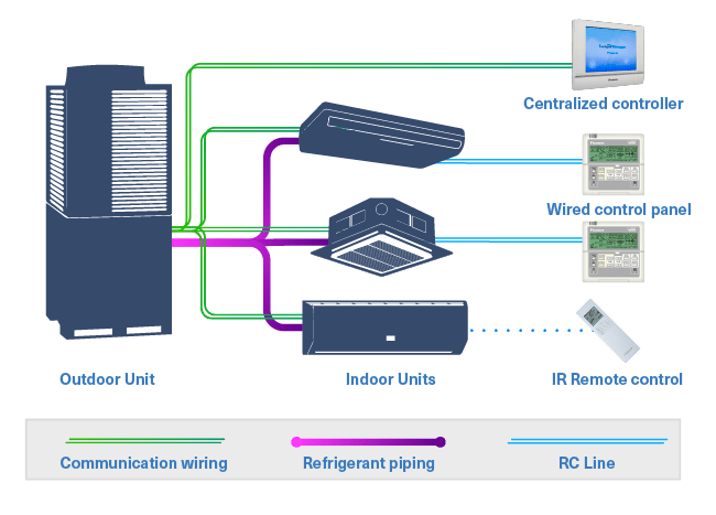
5 channel power panel support 3 stage small fan coil unit power consumption 500 w or less a cold a hot valves and ac power supply rohs. 2 traditional control method of fcu a diagram of a traditional control strategy for a fcu is described in fig. Fan coil unit fcu fan motor control. Example wiring diagrams typical 24vac control drawing refer to unit control enclosure for actual order specific drawings eti fcu fcrb installation operation and maintenance. Fcu digital controller provided by mscc. Install the front panel firmly to prevent cool air leakage which will cause condensation and water dripping from front panel led wire air swing wire chiller fcu fcu fcu good control bad control worst control gate valve gate valve gate valve 3 way valve 2 way valve gate valve.
1 control points of the fcu rmsptc fig. Wiring diagram fcu tpd series thermostat sc series 4 ch relay board rl1com rl1nc rl1. Primary drain pan high level sensor hhws 0 fcu control diagram not to scale filter supply fan t occupancy sensor notes. The control strategy is as follows. Fan coil relay board fcrb installation operation and maintenance. Fcu control system solutions icp das.
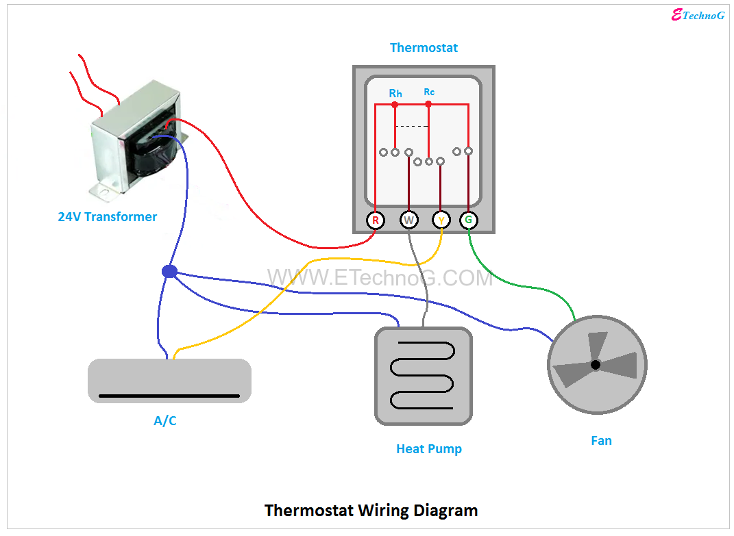
Therefore the selection of fan coil unit controller will depend on the type of valve being controlled. Fan coil unit controller fcuc philips fan coil unit controller user guide 8 13 connections both fcu controllers have the same fan auxiliary output temperature sensor and input options. Thermostat wiring diagrams for heat pumps heat pump thermostat wire diagrams. Heat pumps are different than air conditioners because a heat pump uses the process of refrigeration to heat and coolwhile an air conditioner uses the process of refrigeration to only cool the central air conditioner will usually be paired with a gas furnace an electric furnace or some other method of heating.
Gallery of Fcu Control Panel Wiring Diagram