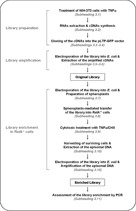
Notifier nfs manual online. A wiring diagram is a simplified conventional pictorial representation of an electric circuit.
Notifier Fcm 1 Wiring Diagram General Wiring Diagram
Fcm 1 rel wiring diagram. Notifier nfse manual online. It will then enter a 3 second window awaiting a pair of confirmation signals. Secure module to electrical box supplied by installer as shown in figure 2. 5 for frm 1 general fcm 1 control module the fcm 1 addressable control module provides notifier intelligent control pan els a circuit for notification appliances horns strobes speak ers etc or to monitor a telephone circuit. Connecting a releasing device to the fcm 1 rel. 4675 h x 4275 w x 14 d mounts to a 4 square by 218 deep box specifications for frm 1.
Fcm 1 rel wiring diagram wiring diagram is a simplified customary pictorial representation of an electrical circuit. Set the address on the module per job drawings. It reveals the parts of the circuit as streamlined forms and the power as well as signal links in between the tools. Dn 6724 040504 page 1 of 4 fcm 1 module see wiring diagram fig. Variety of notifier fcm 1 wiring diagram. Maximum slc current draw.
16112018 16112018 3 comments on notifier fcm 1 wiring diagram. Releasing control module smb500. The module must be armed with a pair of signals in order to activate. This module can be used to replace a cmx 2 mod ule that has been configured for supervised wiring operation. 65 ma led on temperature range. Control module barrier required by ul for sepa rating power limited and non power limited wiring in the same junction box as fcm 1 rel.
Notifier fcm 1 wiring diagram. The fcm 1 has two pairs of output termination points available for fault tolerant wiring and a panel controlled led indicator. When using the fcm 1 rel for class b applications remove jumper j1 and discard. Compatibility requirements to ensure proper operation this module shall be connected to a. Install module wiring in accordance with the job drawings and appropriate wiring diagrams. Releasing applications c limited energy cable cannot be used to wire a.
32f to 120f 0c to 49c dimensions. It shows the components of the circuit as simplified shapes and the gift and signal contacts amongst the devices. If no confirmation is received the module will automatically reset. Maximum slc current draw. Control module barrier required by ul for sepa rating power limited and non power limited wiring in the same junction box as fcm 1 rel. The fcm 1 rel releasing control module uses a redundant protocol.
15 to 32 vdc. Connecting a releasing device to a fcm 1 module connecting an. 15 to 32 vdc.
Gallery of Fcm 1 Rel Wiring Diagram