Media case studies. The 7100 series is intended for commercial industrial and institutional installations the.

Innovairflex Series Dnr Dnrw Duct Smoke Housing
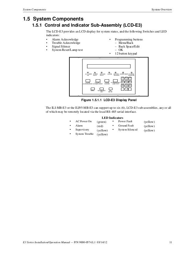
Fci 7100 wiring diagram. 6 thoughts on lcd 7100 annunciator wiring diagram. It reveals the elements of the circuit as simplified forms as well as the power as well as signal links in between the tools. Figure 11 illustrates the 7100 series sub assembly. The 7100 series fire alarm control panel is a multi processor based analog addressable system. It shows the parts of the circuit as simplified shapes and the power as well as signal links in between the gadgets. It is available with either one or two signaling line circuits.
Fci lcd 7100 wiring diagram what is a wiring diagram. See fci publication pn 9000 0427 for a list of approved sensors and bases. Variety of fci lcd 7100 wiring diagram. All illustrations functional descriptions operating and installation proce dures and other relevant information are contained in this manual. It shows how the electrical wires are interconnected and may also show where fixtures and components could possibly be connected to the system. The control panel is a compact yet expandable platform that reflects gamewell fcis building block approach to cost effective life safety system solutions.
Assortment of fci lcd 7100 wiring diagram. If building ownership is. Do not sell my personal information. The gamewell fci 7100 is a multiprocessor based analogaddressable system designed for commercial industrial and institutional fire alarm appl ications. The contents of this manual are important and the manual must be kept with the fire alarm control panel at all times. View online or download honeywell gamewell series installation operating manualfci lcd wiring diagram sample electrical wiring diagramlcd computer wiring wiring diagram pictures.
Fci 7100 series fire alarm control. A wiring diagram is a simplified standard pictorial representation of an electric circuit. A wiring diagram is a straightforward visual representation with the physical connections and physical layout of an electrical system or circuit. All illustrations functional descriptions operating and installation procedures and other relevant information are contained in this manual. Listed factory mutual approved analog sensors and bases. Fci 7100 series fire alarm control.
A wiring diagram is a streamlined standard pictorial depiction of an electric circuit. Each signaling line circuit can accommodate 99 sensor address points using address numbers 01 to 99. The 7100 accommodates only fci approved ul. The contents of this manual are important and the manual must be kept with the fire alarm control panel at all times.
