And why not the other way. Consider support via donation from the link upper right.
Light Switch Wiring Diagram Boat Diagram Base Website Diagram
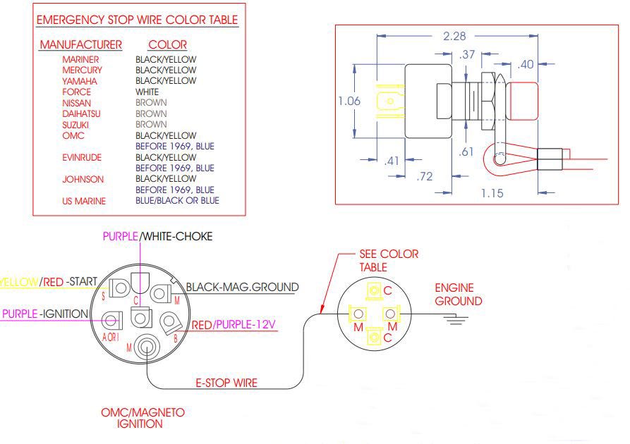
Estop wiring diagram. Next is joining the some of the wires together. In an emergency situation the e stop button is pushed and the device powers down. A wiring diagram is a streamlined traditional photographic depiction of an electrical circuit. The timing diagram in figure 6 shows the sequence of events when the estop is closed and the reset button is pressed. In this episode we will learn how emergency push buttons are wired the correct way. Figure 5 shows the wiring for a typical category 4 estop two contacts or channels on the estop.
Video is incorrect this video only applys to machines running grbl users with a duet controller please follow our guides here. It shows the parts of the circuit as simplified forms as well as the power as well as signal links in between the gadgets. If you are referring to the physical e stop switch as opposed to one in software such as in mach3 then all you really need to do is connect it to the power leg of your machine between the power inlet and the major components. Otherwise the structure will not function as it ought to be. L the schematic or line diagram includes all the components of the control circuit and indicates their. They typically are used in work environments where a potentially harmful device is used by an operator.
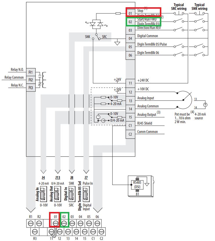
Plus when you bend the wire into a curved shape it retains it better. Variety of emergency stop button wiring diagram. Vfd start stop wiring diagram. For correct wiring please see wiring diagram below. An e stop or emergency stop button provides a quick way to disconnect the power for any device. Look at this wiring diagram.
Each component should be set and linked to different parts in specific manner. Vfd is a short form of variable frequency drive or variable voltage variable frequency drivethe vfds are working based on changing the input frequency and input voltage of the motor we can change the speed of the. The basic circuit diagram shows which wires go on the switch and which ones are joined together. Iec diagram a1 t11 t12 t31 t34 t22 t35 13 23 33 43 53 61 73 a2 x1 x2 t33 14 24 34 44 54 62 74 t32 b1 b2. How to wire a e stop. Motor starter wiring diagram start stop motor starter wiring diagram start stop every electrical arrangement is composed of various distinct pieces.
The solder on the wire provided mechanical strength and keeps the wires together when the screw is tightened down. Typical wiring diagrams for push button control stations 3 genera information at each circuit is illustrated with a control circuit continued schematic or line diagram and a control station wiring diagram. I am here with giving you a vfd start stop wiring diagram for running a vfd through panel board push button and keypad of the vfd it is called hmi.
Gallery of Estop Wiring Diagram