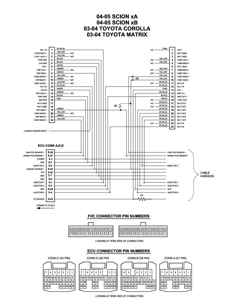
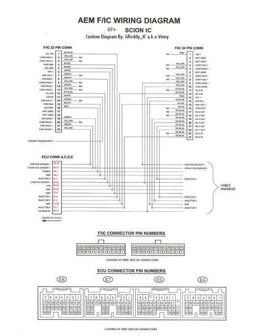
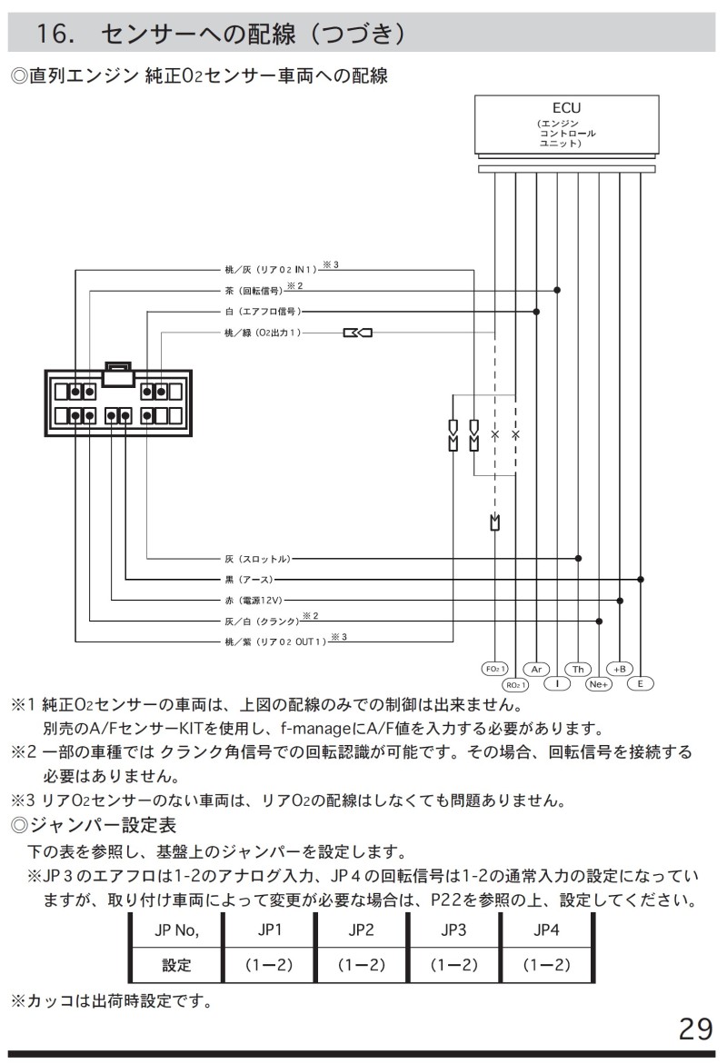
Vtec idle control valve 14 8. E manage ultimate wiring and setup wiring diagram 1.
Ultimate Emu Install Writeup Tuning Www Ka T Org
Emanage ultimate wiring diagram. Never tune the e manage ultimate on public highways. E manage ultimate pin diagram connectors a and b are the same as the e manage. Vtec idle control valve 15. The greddy e manage ultimate is as close to a stand alone management system as you can get while maintaining the best features of a piggy back engine management. Harness diagram 11 6. The e manage ultimate has added connector c for more functions.
E manage ultimate automobile accessories pdf manual download. Wiring whatever you do dont look at the ecu wire location chart at the back of the emanage manual. Any help would be greatly appreciated. Hey guys was wondering if any of you have found the correct wiring diagram for the greddy e manage ultimate that is delivered with the charger kit. An economical price the usage of existing sensors the ability to easily alter factory settings and not having to tune from scratchbut unlike the original e manage the ultimate is more refined requiring specific application. The initial installation consists of the same basic connections as an apex afc.
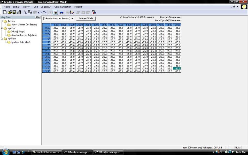
Injector w iring the e manage ultimate has upgraded the injector adjustment feature. It is completely wrong and is only there to confuse you. The guy i bought it from got it for a different car so it wont come with a wiring diagram but it does have a universal wiring harness. We have 1 greddy e manage ultimate manual available for free pdf download. When connecting the connector push it in all the way until you hear them click in together. Ignition signal wire.
Never tune the e manage ultimate while the vehicle is moving. Discussion starter 1 jul 2 2011 edited hi guysjust for thoses whore looking for the e manage ultimate wiring diagram for the 2001 models and 2002 2005 here it is. 9 vanderbilt irvine ca 92618. I just bought an e manage ultimate and i am planning on putting it on my 04 celica gt s. Engine control unit manager. Wiring power ground airflow meterthrottle rpm signal for rb26dett with 2 airflow.
Injector wires 15 16. Can anyone get me a pic of their diagram or give any advise on what. View and download greddy e manage ultimate installation manual online. Wiring power ground airflow meter throttle rpm signal 1213 7. Apparently the ecu diagram in the instructions is totally mismatched and wrong. Ignition signal wire 17 18.
Wiring power ground airflow meter throttle rpm signal 1213 7. Wiring power ground airflow meter throttle rpm signal 1213 14. Injector wires 15 16 9. 2001 and 2002 2005 is300 e manage ultimate wiring diagram. Read and fully understand the wiring diagram before making any wire connection. Joined aug 17 2004 200 posts.
Jump to latest follow 1 5 of 5 posts. These are power ground rpm signal throttle position signal airflow input and airflow output. This can be dangerous to you and others on the road. If there are any questions regarding this products please contact your greddy authorized dealers or greddy performance products inc.


