The rear view is the end you solder from here are the connections on each pin. Available for 1 34 to.
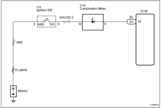
Toyota Sienna Service Manual Mil Circuit Diagnostic
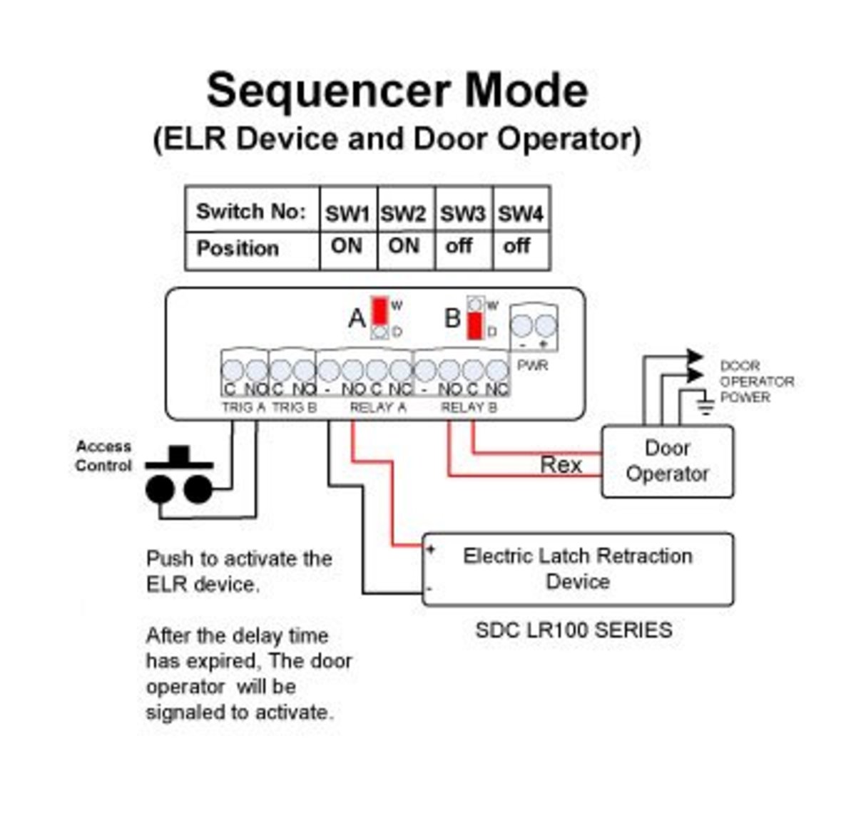
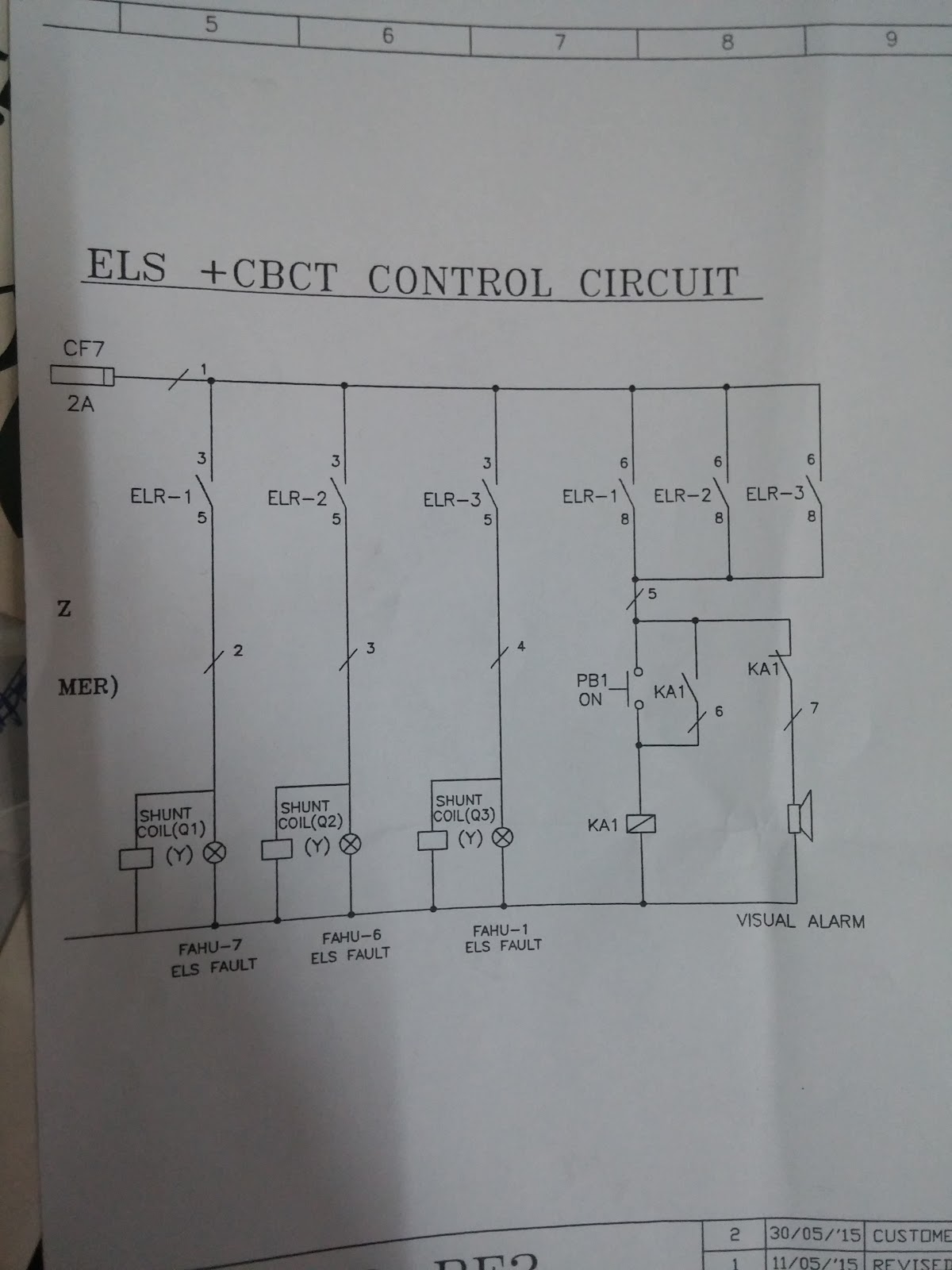
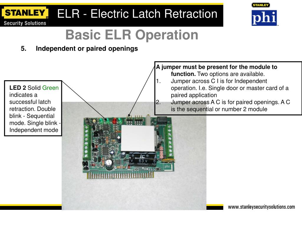
Elr wiring diagram. 4 apex 2000 series devices rim exit devices apex 2100 series reversible apex fl2100 fire exit series reversible apex 21 series nonhanded rim exit devices doors for all types of single and double doors with a mullion. Wiring diagram for el devices with automatic operator and safety. 3 1 2 fault 1. The cbct zct mounted externally and load current carrying cable is passed through the cbct zct. A residual current causes a flow unbalance detected by the toroid 2. Its removable wiring terminals rends it very easytoinstall.
The elr 7 has a microswitch to select the working mode of the end relay normally de energized whilst at rest no tripped condition or normally energized fail safe. On top of the above it also has 2 change over separated and a transparent front cover for protection. For additional questions contact the technical services team at 800 810 wire. The residual current relay receives the signal from. If those diagrams do not meet your requirements a custom order can be placed by authorized dealers only using the wiring diagram order form. How is a elr or panic device wired to a senior swing.
The above diagram shows you the pin numbering for both male and female xlr connectors from the front and the rear view. Connect the gray wire to the sc terminal on the 900 2rs card in the von duprin power supply and the violet wire to the i1 terminal. Elr3c 10 reset 4 txio 1b o tx1 xl 1 co xo11a1 x 10 1 d o elr 3c description 1 current tripping setting potentiometer. The new range of elr products from abb comply with iec en 60947 2 annex m and is tested within a configuration that includes residual current relay toroid shunt trip mccbmcb available in abb offer. Standard wiring diagrams are available at no cost. 3 pin xlr connectors are standard amongst line level and mic level audio applications.
In this i try to give better understanding about earth leakage relay elr and core balance current transformer cbct how to wire elr and cbct with mccb and the working principle of elr. Cbct zct only principle of operation earth leakage relayelr employs a core balance current transformer cbct zct to sense the leakage current. El devices are wired to the senior swing using the p10 761465 cable. Ideally in a leakage free. Wiring diagram dimensions earth leakage relay eelr 3clr 3c electrical characteristics auxiliary voltage supply frequency 50 60hz maximum consumption. 30 300 ma 50 2000ma 30 3000 ma elr is available upto 150 mm id.
Order a custom wiring diagram. For mullions see page 18. 3 pin xlr wiring standard. Single door controlled egress wiring diagram 01 single door digital entry wiring diagram 10 single door dk 26 with door prop alarm wiring diagram 15 single door dk1 11 xms dt 7 wiring diagram 20 single door dk 26 remote release wiring diagram 14 single door dk 26 unl 24 and dt 7 wiring diagram 18 single door dk 26 using the hard code to toggle lock off and on wiring diagram.
