Wcc and wbb available for all single gang push buttons keyswitches and keypads. 18 awg 10 ft.

3ds Max Help Polydraw Panel
Eeb2 wiring diagram. 18 awg 15 ft. Eeb2 mag 4 cond. 18 awg 15 ft. Single door controlled egress wiring diagram 01 single door digital entry wiring diagram 10 single door dk 26 with door prop alarm wiring diagram 15 single door dk1 11 xms dt 7 wiring diagram 20 single door dk 26 remote release wiring diagram 14 single door dk 26 unl 24 and dt 7 wiring diagram 18 single door dk 26 using the hard code to toggle lock off and on wiring diagram. Laying out the circuit diagram team system project open discussion and questions access control the basics exiting switches existing. 18 awg 15 ft.
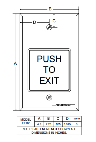
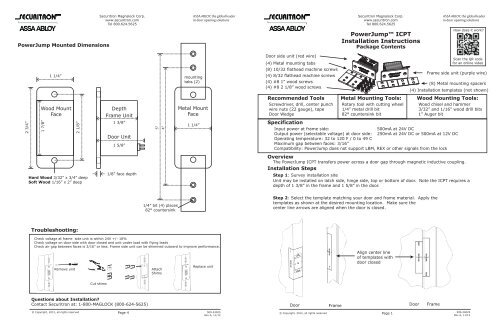
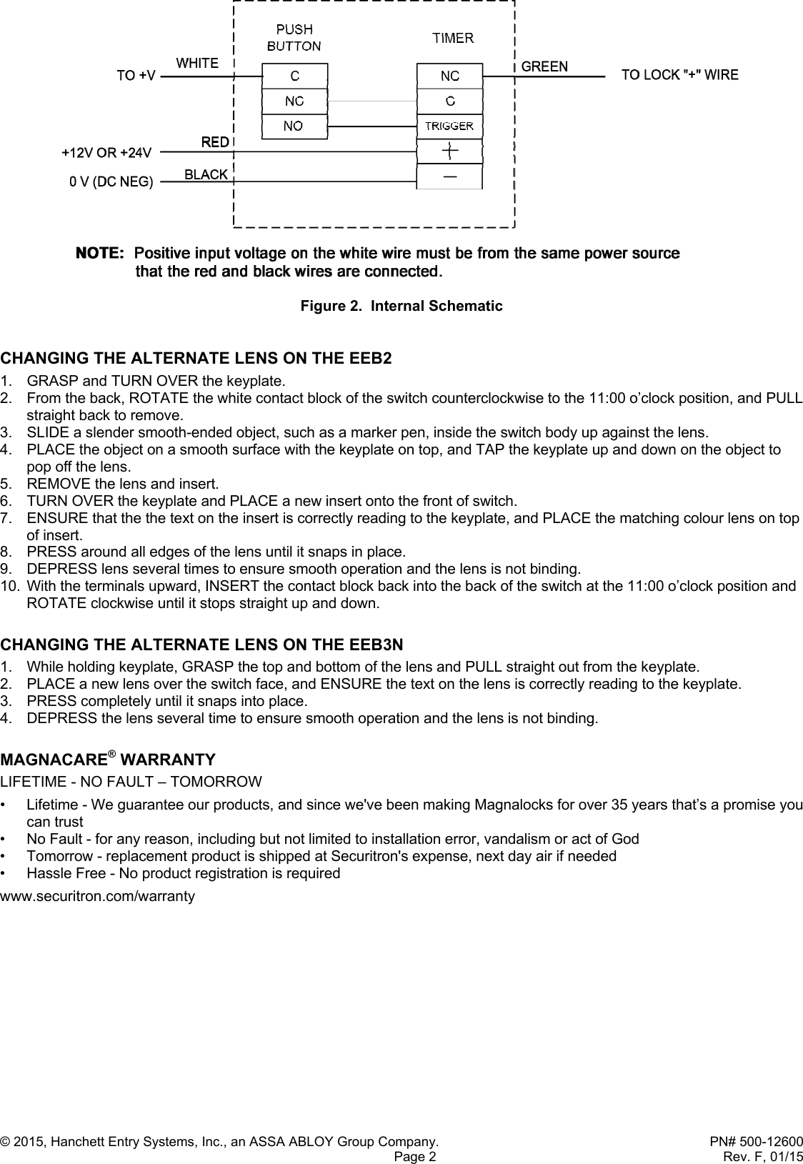
The eeb2 comes with a retrofit backbox fasteners and color coded hookup wires installed. The eeb2 and eeb3n operate on 12 vdc or 24 vdc and can accept the use of full wave rectified dc transformer and bridge rectifier. Positive input voltage on the white wire must be from same power source that the red black wires are connected to. The red and white wires from the eeb23n must receive voltage from the same power supply. The backbox securitron part number 560 10200 includes an installation template. Identification of the wires and a typical wiring diagram showing a power supply motion detector push button and magnalock so as to comply with the boca code for access.
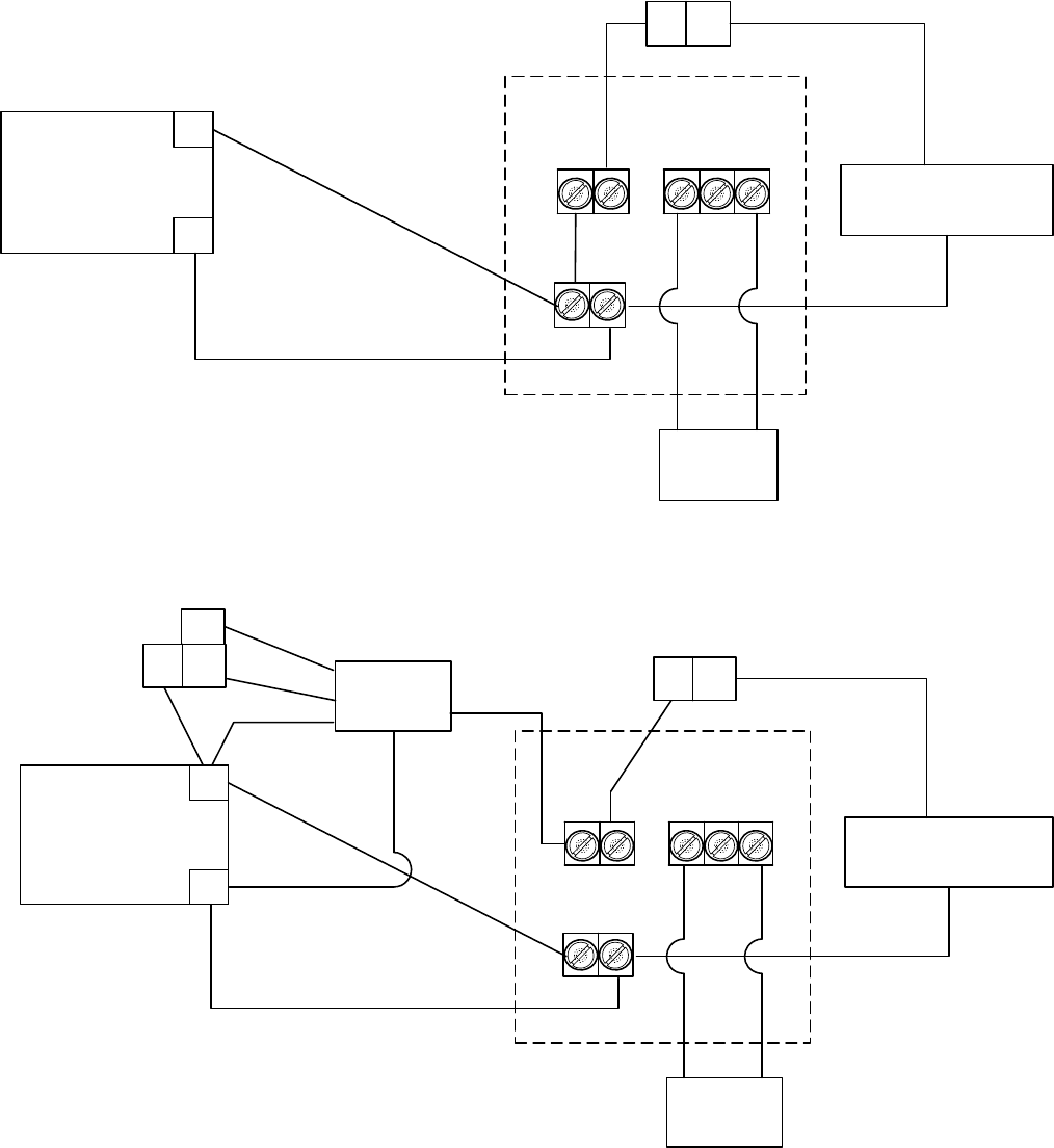
Securitrons ul294 certification indicates that when the eeb is used with the xms motion sensor it meets the nfpa life safety code 101 requirements for exit of access controlled egress doors. Wire identification and typical hookup red black green white eeb2 or eeb3n 12v or 24v 0v dc neg to lock wire to v power supply xms device in white red black eeb2 or eeb3n green re d magna lock black note. Wiring circuit lets make it work. Wiring the eeb2 and eeb3n caution the eeb2 and eeb3n can be damaged if operated on 24 vdc with the jumper in place or operated on a power supply different than what is operating the magnetic lock. Pir 170ma 6a 1250 ma.
Gallery of Eeb2 Wiring Diagram