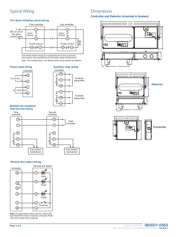
Note 1 this component is the fire resistor and its value is specified by the fire control panel manufacturer. 721u two wire photoelectric smoke detector with remote test input and remote alarmtrouble led output 721ut two wire photoelectric with rate of rise heat detector.

Edwards Est3 Fire Alarm Panel Disable And Enable Active Point
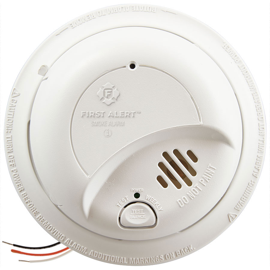
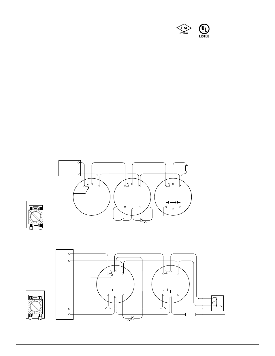
Edwards smoke detector wiring diagram. In our basic wiring diagram a single or multiple heat and smoke detectors are installed in the home by connecting the live line or hot neutral ground and an interconnected wire to the alarm. All wiring should use the cables approved by the fire alarm system manufacturer. Edwards recommended cables are shown in table 1. Wiring diagrams provided herein are for information and reference only and are not to be used for installation pur poses. Riser diagram and wire pull for some commonly used fire alarm circuits. Consult the appropriate installation documents for wiring and configuration details.
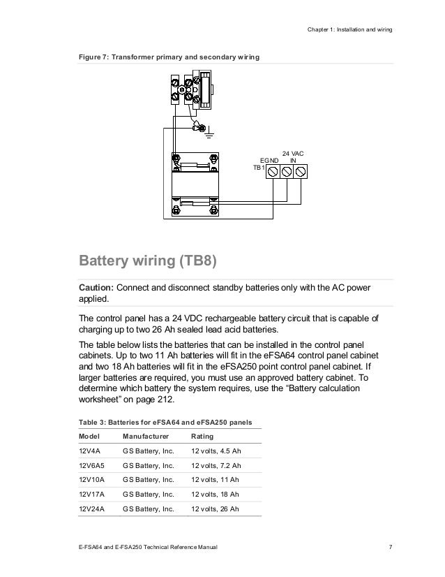
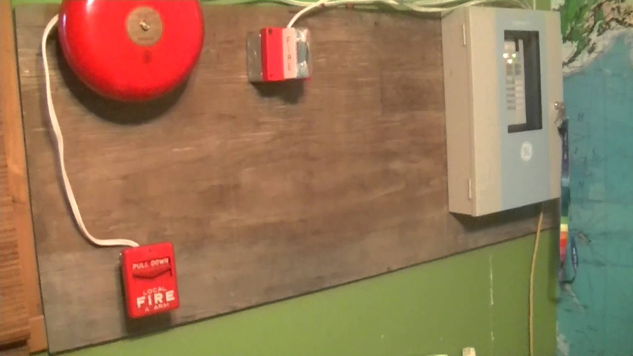
Dress the wiring neatly and then verify that the continuity. This is the basic fire alarm system used in household wiring. For us installations it is typically a short circuit. When a smoke detector or pull station operates. A smoke or heat detector can be installed to the existing or new home wiring. To the appropriate terminals according to the wiring diagrams see figure 6 or figure 7.
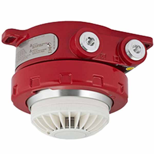
Optical beam smoke detector. Designed for easy installation and superb reliability superduct represents the perfect balance of practical design and advanced technology. Wiring diagram for connection of a single conventional detector to a zone. Edwards signaling catalog u conventional initiating 06 27 13 mea two wire duct smoke detector superduct series overview superduct is slim feature rich alternative to bulky duct smoke detectors.
Gallery of Edwards Smoke Detector Wiring Diagram