Starter type bucket width and door width can assist in identification. Assortment of eaton mcc bucket wiring diagram.
Eaton Control Transformer Wiring Diagram Diagram Base
Eaton mcc bucket wiring diagram. Eaton motor starter wiring diagram 40 awesome square d model 6 mcc wiring diagram motor control center aftermarket buckets eaton. It shows the components of the circuit as simplified forms as well as the power as well as signal links between the devices. December 2002 page 3 motor control center type series 21005 star identifying motor control center types in most cases it is possible to identify mcc design by handle type. They can be used as a guide when wiring the controller. They show the relative location of the components. Rp04304003e for more information visit.
In the event that the nameplate is missing or unreadable follow the procedure on page 4. A wiring diagram is a streamlined traditional pictorial depiction of an electric circuit. Variety of eaton mcc bucket wiring diagram. Wiring diagram images detail. The freedom line combines intelligent communications and industry leading arc flash prevention to group motor control distribution equipment industrial communications and associated. With over 80 years of experience designing and manufacturing motor control centers eatons mcc aftermarket team has built an expertise at providing custom aftermarket solutions for the widespread applications of our customers.
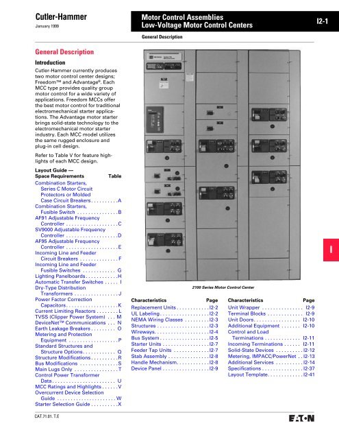
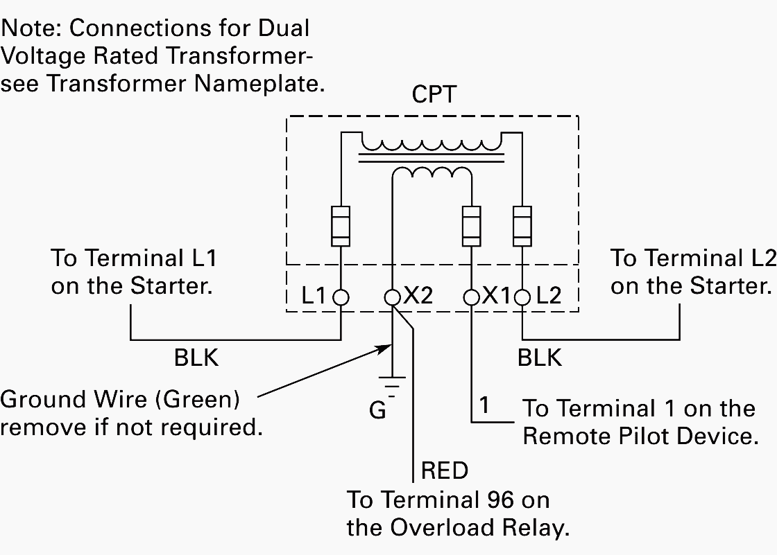
Figure 1 is a typical wiring diagram for a three phase mag. Refer to pages 6 24 and. Mcc web wiring drawings. Full voltage reversing starter. Identify the design of the eatons cutler hammer motor control center mcc from the data found on the nameplate. Eatons motor control centers mccs and mcc aftermarket solutions provide customers with a variety of safe cost effective and industry leading options.
Fvnr freedom full voltage non reversing select another application locate the drawing number using the drop downs to filter the results. It shows the parts of the circuit as simplified shapes and the power and signal links in between the tools. Full voltage non reversing starter fvr flashgard. A wiring diagram is a simplified conventional pictorial representation of an electrical circuit. Wiring diagrams sometimes called main or construc tion diagrams show the actual connection points for the wires to the components and terminals of the controller.
Gallery of Eaton Mcc Bucket Wiring Diagram


__37446.1577471817.jpg?c=2)