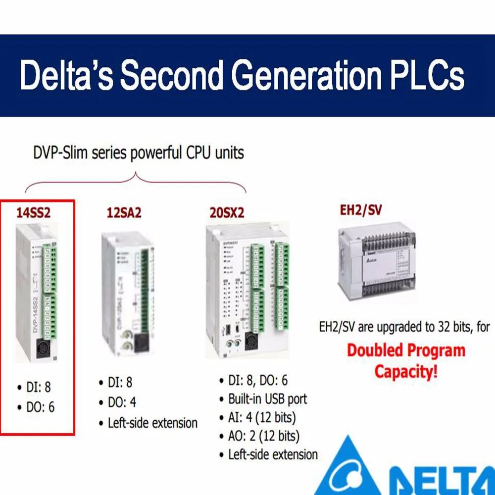
Ladder diagram complied into instruction ladder diagram complied into instruction 1 15 dvp plc application manual. The dvp ss2 series is delta electronics second generation of slimline industrial plcs.
Download Delta Wplsoft Manual Chm Manual Plc Ladder
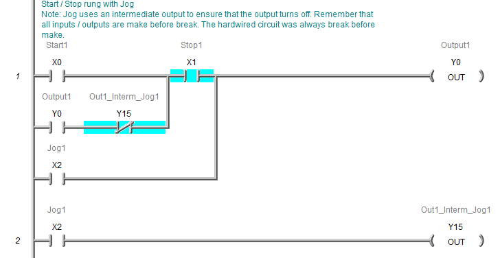
Delta dvp 14ss2 wiring diagram. March 29 2016 at 855 am. This symbol identifies a note about a situation where damage to a. The 2nd generation dvp ss2 series slim type plc keeps the basic sequential control functions from the dvp ss series plc but with faster execution speed and enhanced real time monitoring capability. Due to that diagram a is illegal there is a reverse flow in it. Delta 12 se series has 8 digital input points and 4 digital output points. In diagram a the block on top is shorter than the block in the bottom we can switch the position of the two blocks to achieve the same logic.
View online or download delta dvp ss2 operation manual. Delta dvp ss2 pdf user manuals. Delta se series has 2 type. Purchase your delta dvp ss2 series today. My plc is delta dvp 24es2 and my system software is dop. In this video the connection to the wiring of delta plc dvp 14ss2 has been done with an easy way.
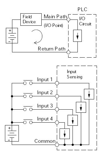
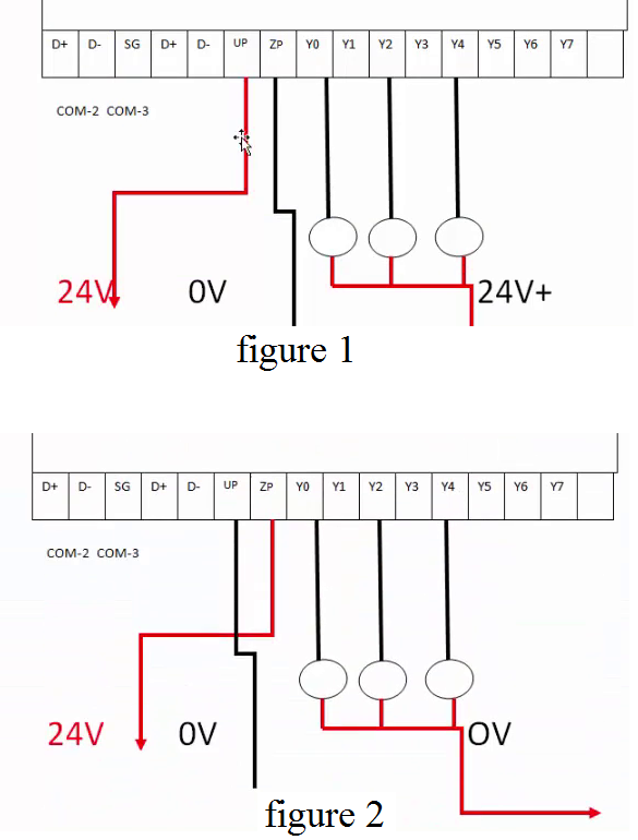
Delta controls has written wiring and installation guidelines to provide its partners with a primary source of recommended practices for wiring power inputs and outputs and networks for delta controls products. Automatedpt can assist you in the development of power transmission systems to include machine retrofits applying industrial gear motors brakes clutchs and applying electrical or electronic motor controls and hmi interface applications. Plc inputs can be connect in either sink mode or source mode. Sir these cable diagram can be used for dvp ss plc. In a rs 485 connection between a pc and a dvp 14ss2 wiht expansion module dvp 16sp i have a problem reading the memory address from dvp 16sp inputs. Power input of delta se is dc.
The dvp 14ss211r features high speed counters a flexible serial port real time monitoring and an expansion bus that allows matching modules to be mounted on the right side of the plc without external wiring. This video describes how to wire your controller.
Gallery of Delta Dvp 14ss2 Wiring Diagram