Confused by danfoss wiring diagram. The set2e is a direct replacement for a danfoss randall set2.
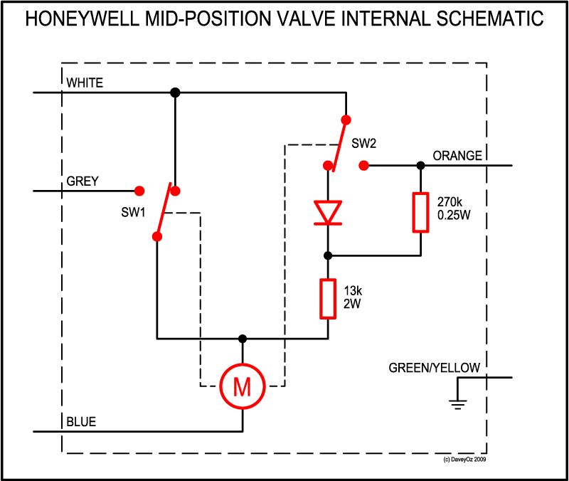
Mid Position Valve Wiring Diagram File Ch Y Plan Mid Pos
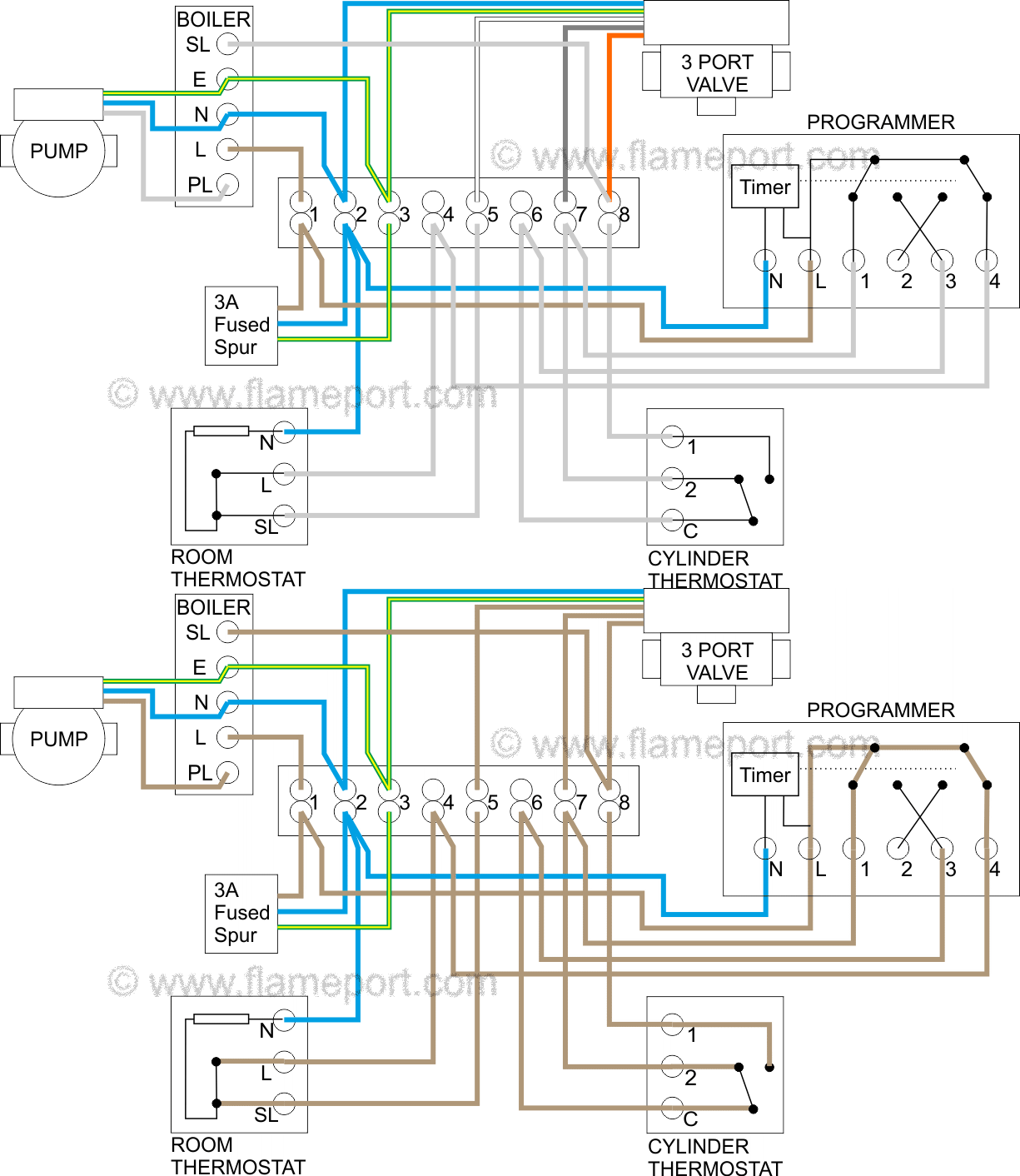
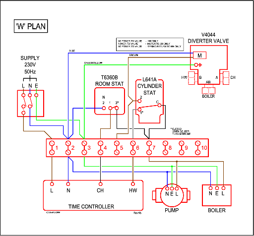
Danfoss y plan wiring diagram. This diagram shows the wiring layout using the most typical components. Only three wires coming from wire to wiring box red yellow blue. The second one that i visited had a room stat wired incorrectly. V4073a y plan how a mid position valve operates within a y plan heating system how a w plan heating system operates faq pump overrun wiring diagrams for s plan incorporating a st9400 programmer. Central heating wiring diagrams danfoss central heating wiring diagrams 3 port mid position valve please note we do not accept any responsibility for the accuracy of any of the diagrams literature or manuals and information may have been supercededamended. Sw l to nc.
Contact the danfoss randall technical services department for details. The wiring diagram shows an external pump. Jackthom 6 nov 2011 5. This video covers the wiring and electrical operation of a y plan system. L to l. Danfoss central heating wiring diagrams for more information see the danfoss wiring guide.
If the unit is to be used in association with a 6 wire honeywell y plan a special wiring diagram may be required. From looking at the diagram y plan red should go to 1 live yellow should go to 2 switched live blue should go to 4 neutral is this correct. Central heating wiring diagrams. Plumber has supplied the danfoss. 3 dec 2010 messages. I have checked the wiring against the danfoss wiring diagram and they seem to be wird correctly.
Danfoss y plan problem. Work must be completed by qualified electricians or heating engineers. Hi guys got to wire a y plan monday and am a litle unsure. Danfoss y plan problem sign in to follow this. Here coloured wires indicate the permanent mains supply to the boiler and programmer. Wiring diagrams and further information continues below.


