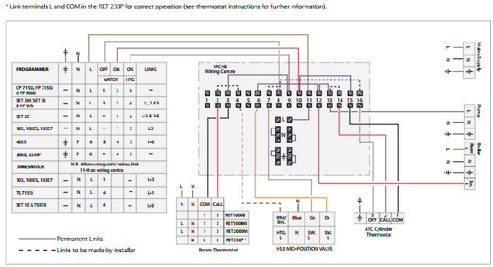
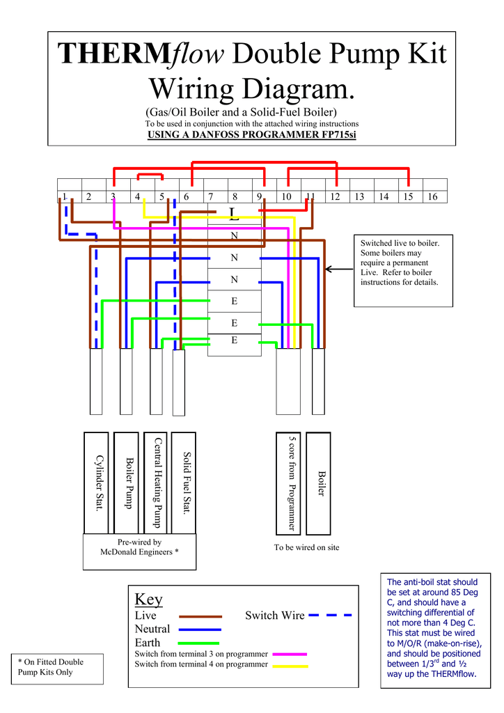
About danfoss contact us home page. Danfoss fp715si programmer wiring diagram the diagrams below show typical wiring circuits with which the wiring conversionsto be used when replacing the following programmers with the fp cp.

Graham Vlt 3500 Wiring Diagram Wiring Diagram
Danfoss wiring diagram. Fc 302 control principle 19 363 control structure in vvc 20 364 control structure in flux sensorless fc 302 only 21 365 control structure in flux with motor feedback fc 302 only 22 contents vlt automationdrive fc 301fc 302 design guide 025 75 kw. Pvg 32 mainly used in system with fixed displacement pumps. I would fit a honeywell and require back to the main wiring center. 7111 fixed variable speed pump wiring diagram 127 7112 lead pump alternation wiring diagram 127 7113 cascade controller wiring diagram 128 7114 startstop conditions 129 8 installation and set up 130 81 installation and set up 130 82 fc protocol overview 131 83 network configuration 132 84 fc protocol message framing structure 132. Danfoss randall can accept no responsibility for possible errors in. Megavolt jan 20 danfoss hsa3 wiring diagram.
View and download danfoss fp installation users instructions online. Mg14i102 vlt is a registered danfoss trademark 1. You can also get inspired by our case studies from around the world or take a deep dive into our training program that can help you advance your career and business. Rsn hpv hpvb 2 port zone valves danfoss randall. Since then the business has grown from a solo enterprise into one of the worlds leading suppliers of energy efficient and innovative solutions. Downloads follow our global channels keep me updated.
35 wiring schematic 16 36 controls 18 361 control principle 18 362 fc 301 vs. Central heating wiring diagrams danfoss controls our engineering tomorrow mindset dates back to september 1 when mads clausen founded danfoss in his parents farmhouse in nordborg denmark. Whether you need help finding technical documentation on our products download software or troubleshoot you have come to the right place. Electrical block diagram for the above illustration w warning it is the responsibility of the equipment manufacturer that the control system incorporated in the machine is declared as being in conformity with the relevant machine directives. 345 terminal tightening torques 26 346 input line connection 26 347 motor wiring 26 348 grounding earthing 27 349 control wiring 27 3410 serial communication bus connection 28 3411 programming 28 4 start up 29 411 inspection before start up 30. 435 cascade controller wiring diagram 105 436 fixed variable speed pump wiring diagram 106 437 lead pump alternation wiring diagram 106 5 special conditions 110 51 manual derating 110 52 derating for long motor cables or cables with larger cross section 111 53 derating for ambient temperature 111 6 typecode and selection 115 contents.
Automotive buildings commercial buildings residential.


