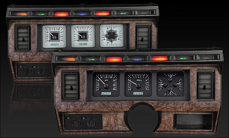
Dakota digital mcl series speedometer so before we cut spliced and soldered we downloaded the oem wiring diagram for this. Dakota digital vhx dash.

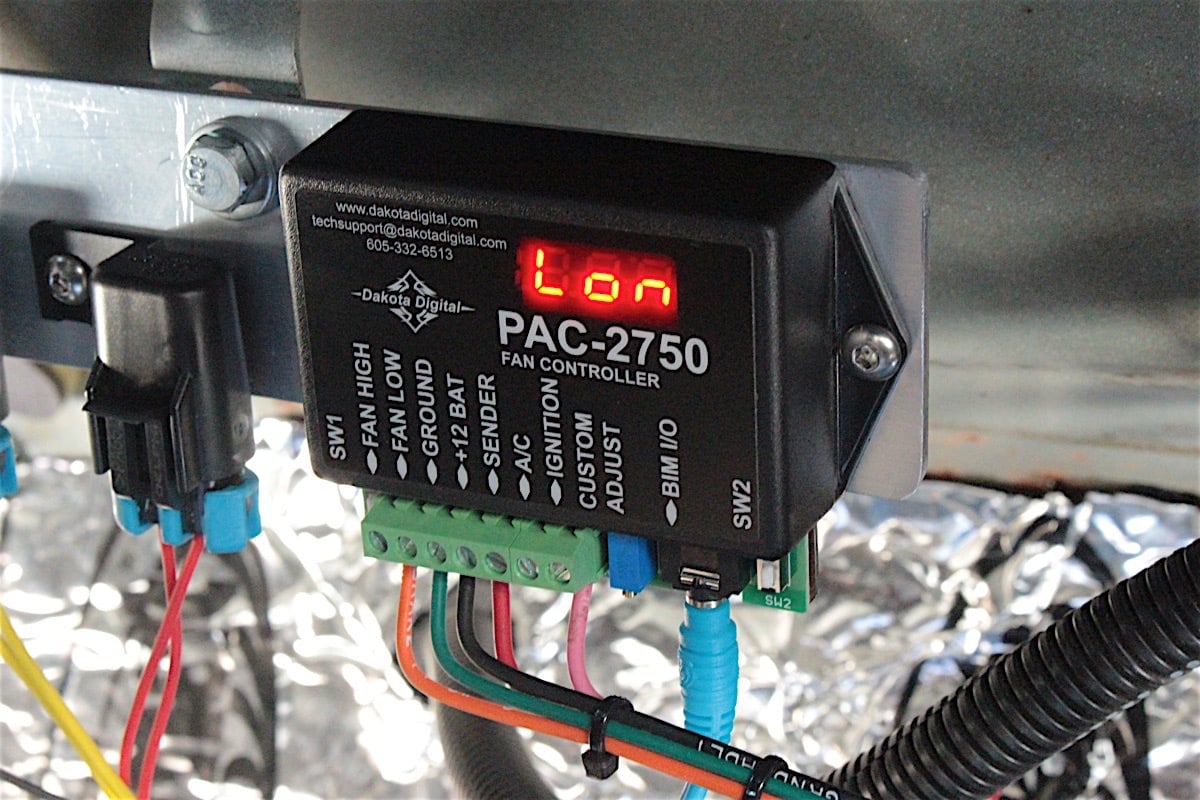
Electric Fan Controller For Cj7 With Mopar Mfi Kit 1972 86
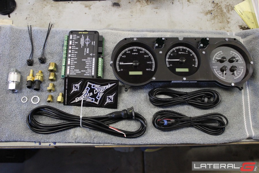
Dakota digital wiring diagram. To cmd 4000 channel output. Speed tachometer fuel level voltmeter water temp and oil pressure. This system can cause your odometer mileage to increase very rapidly if the speedometer is reading too fastthe oil sending unit temperature sending unit and speedometer. The sensor that dakota digital provides is an 8000 ppm type. Dakota digital rly 2 relay pack shown. Once completed all the basic functions should operate.
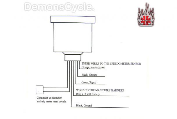
Dakota digital wiring diagram thanks for visiting my site this article will certainly discuss regarding dakota digital wiring diagram. Fused 12v power the wires between the switch and the motor will need to be cut and the relay pack wired. Dakota digital gss unit 1 wire output right turn signal wire optional left turn signal wire high beam wire parking brake switch ut connect to tail light circuit. Quick start wiring diagram this drawing is a quick overview of the basic wiring for your new dakota digital hdx system. For further wiring assistance please read the remainder of the manual. We have collected several images with any luck this photo is useful for you as well as assist you in finding the answer you are looking for.
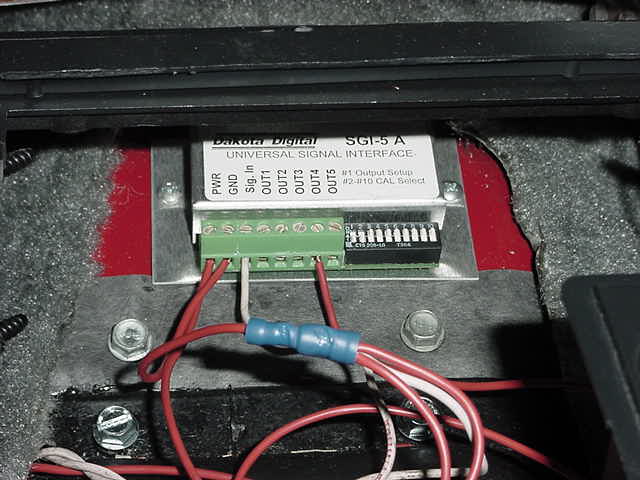
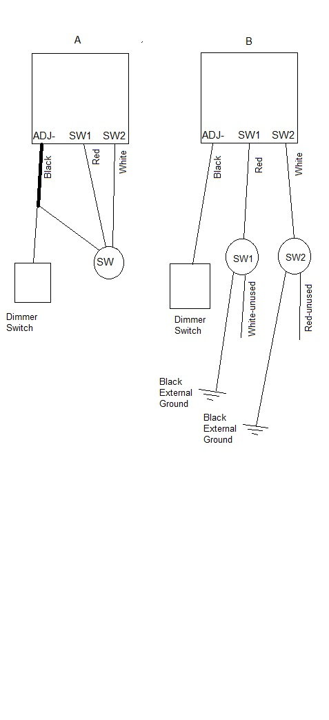
For vehicles which already have a vehicle speed signal tap into the vss wire and connect it to the speed terminal. Connecting decoder to dakota digital control box the 1 wire terminal on the decoder connects to a dakota digital instrument system control box. System switches to night mode when terminal has 12v light or buzzer 4 watts or more tail light light or buzzer 4 watts or less relay exsisting fuel level sensor red. Red wire to the terminal marked red green to green and black wire to black. To cmd 4000 channel output. Diagram to determine wire color and location.
Simply match the wire colors to the labels on the decoder. See graphics below for nomenclature on each generation of control box. You may have to consult a vehicle service manual or wiring diagram to determine wire color and location. Wiring a relay for channels 3456 or 7 87 black blue 86 85 30 green red white wiring to a window motor trunk lift motor or door lock motor. This system can accept 4000 ppm 128000 ppm speed signals.
Gallery of Dakota Digital Wiring Diagram