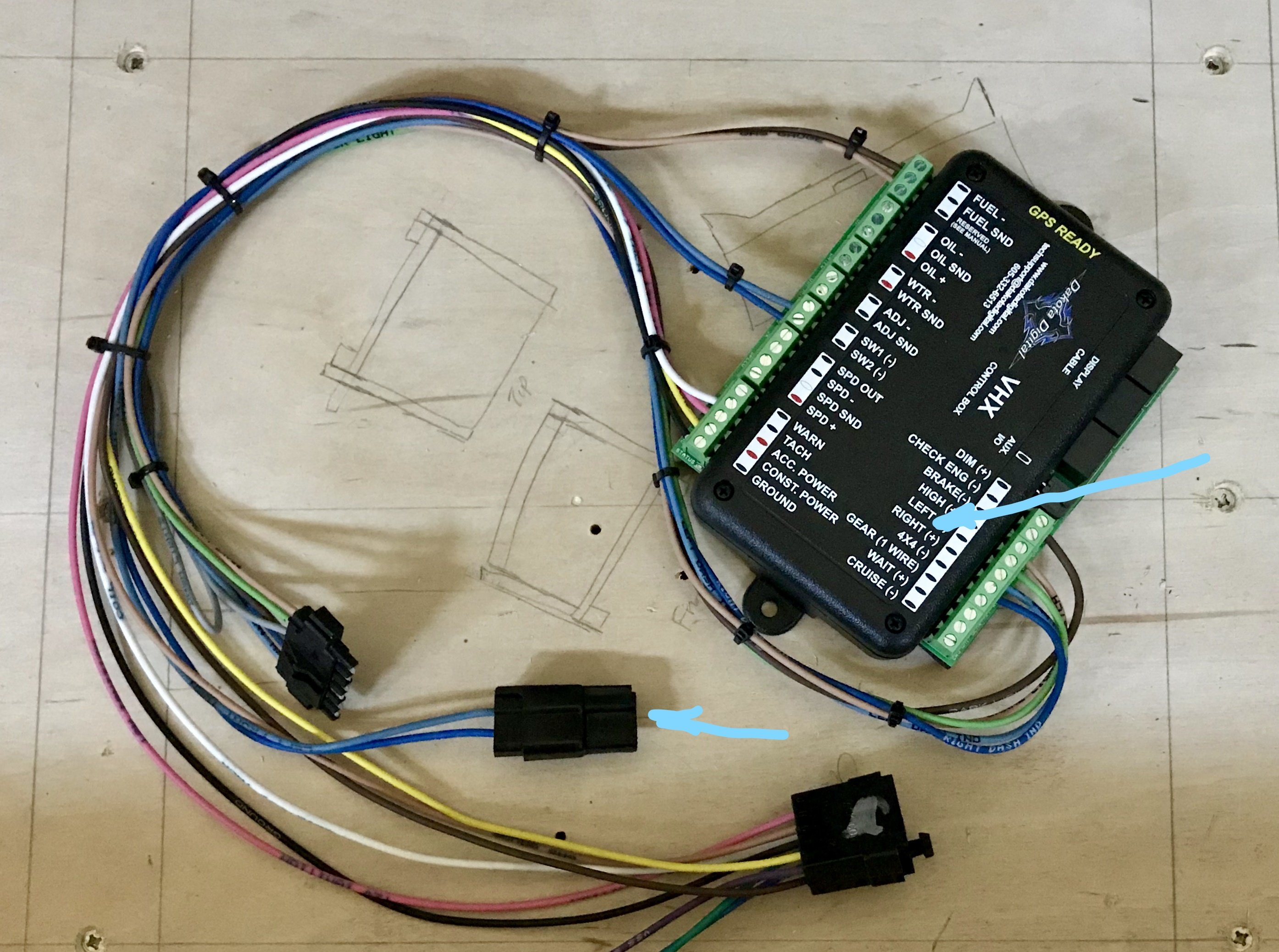
Box measures 4 wide 225 high 1 thick. Choose a mounting location that will allow you access to wire all of the inputs on either side of the control box.

Relays Archives Infinityboxrelays Archives Infinitybox
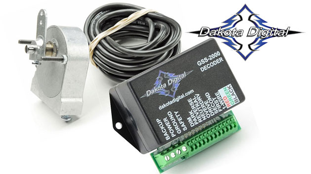
Dakota digital fan controller wiring diagram. This would be a good application for fans fuel pumps and other motors. Bluetooth enabled automatic fan controller bim compatible pac 2750d. A second relay must be ordered if using with dual fans. Dakota digital programmable cooling fan controller. 300ºf sender dakota digital temp sender for operation without a gauge installation. Whats people lookup in this blog.
A second relay is required for dual fan or two speed fan operation. Getting modular dakota digital s electronic fan controller pac 2750 included components installation fan controller question for a bos only mopar forum dakota digital programmable dual fan controllers pac 2750 pac 2750 included components installation. Program dakota digital fan controller for those switching from clutch fans to efans. Fans can be set to turn on between 150 and 250 degress f. If the gauge uses a two wire temperature sender such as autometer full sweep use of a dedicated dakota digital sender is required. Correctly the fan control unit will not have correct temperature information and cannot be guaranteed to properly control the fan possibly leading to overheating and engine damage.
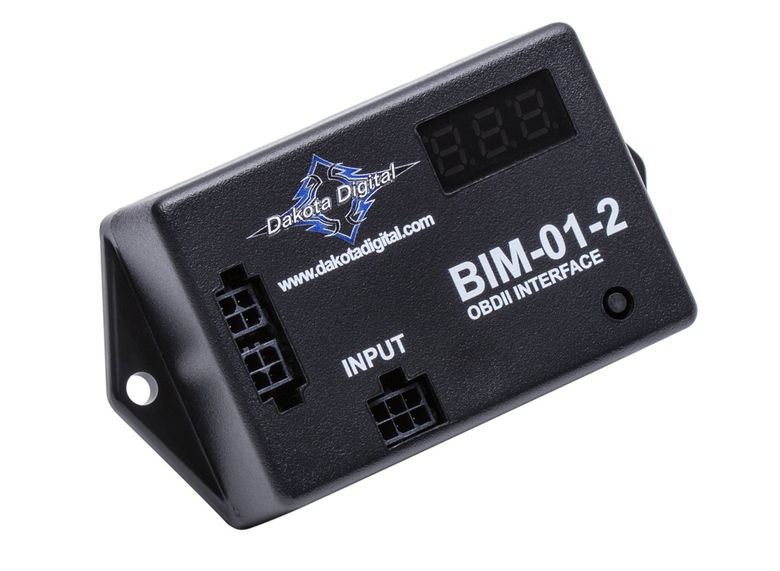
Plastic control box digital clock manual. Figure 4 fan wiring ground switching relay. Dakota digital manufactures digital instrumentation and accessories for the automotive. Mount only in vehicle cabin. When used in conjunction with bim compatible dakota digital instrumentation or a bim 01 2 a single cable transfers speed and temperature data to the pac 2800bt allowing the fan to be shut off at an adjustable highway speed. This controller can be used to operate with a single fan a two speed fan or dual fans.
Control box mounting once the display panel is in place mount the control box within reach of the supplied display cable approximately three 3 feet. Controller is not designed for engine compartment mounting. Dakota digital fan controller wiring diagram. Wiring and operation manual for vfd clocks. Fan high relay connect to the white wire on the high fan relay assembly. Dakota digital manufactures digital instrumentation and accessories for the automotive motorcycle and car audio enthusiast.
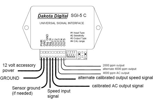
The terminal strip on this unit has 6 connections. The tables below show the appropriate wire colors for dakota digitals rly 1 rly 2 and rly 3 and the corresponding connection number. Wiring and operation instructions. Controller comes with one 70 amp relay. Automatic fan controller bim compatible. Or load as long as the control output is grounded.
Gallery of Dakota Digital Fan Controller Wiring Diagram