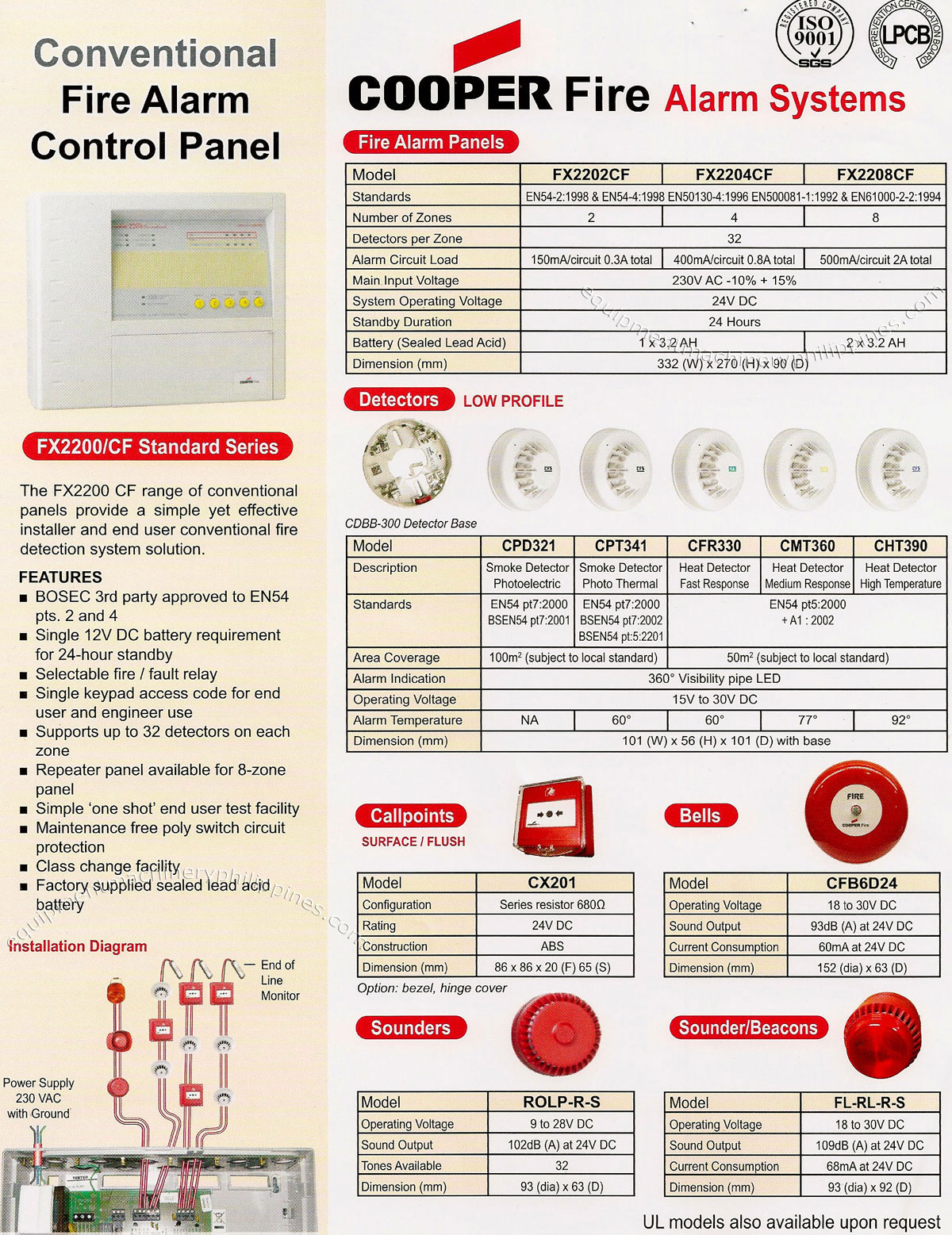
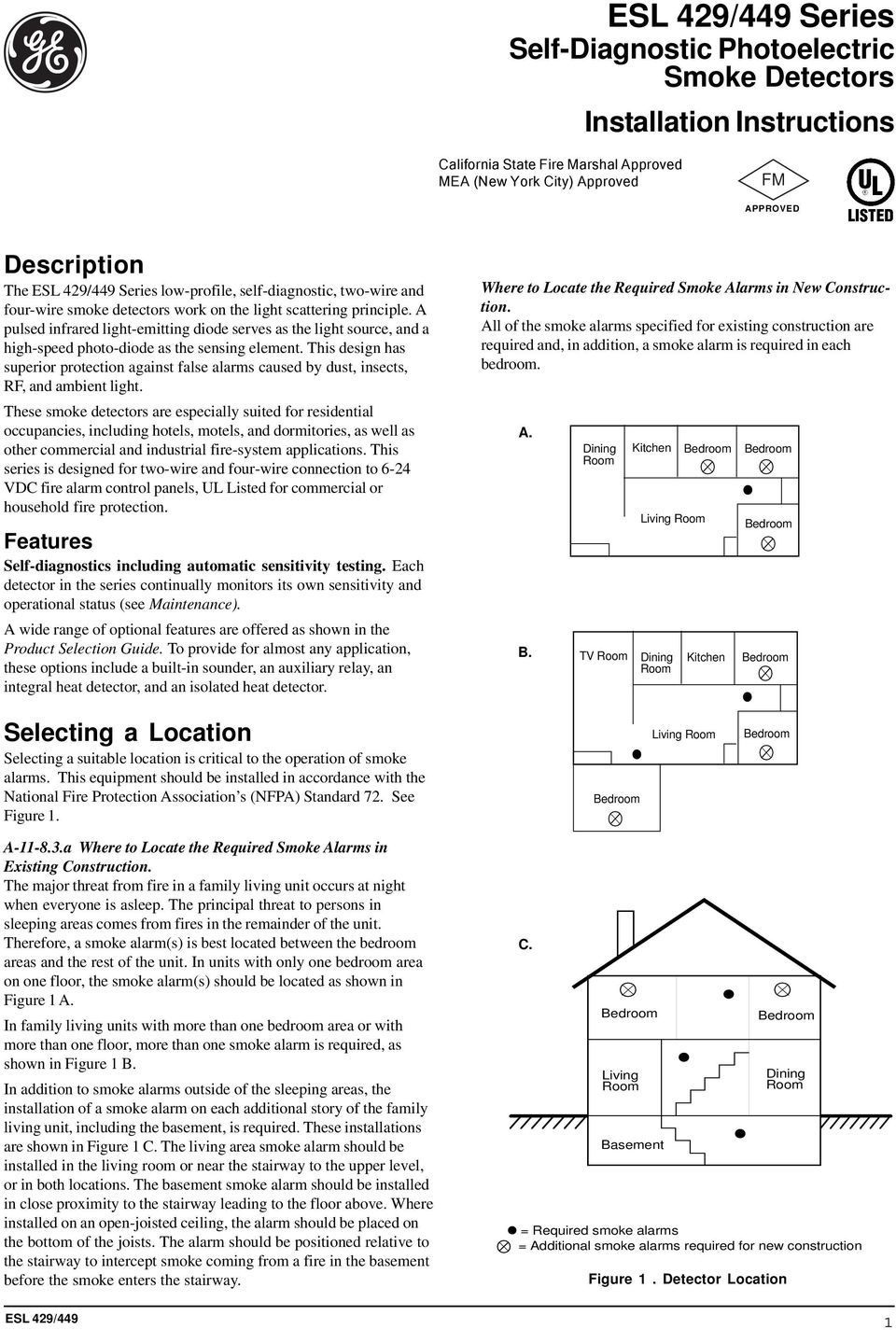
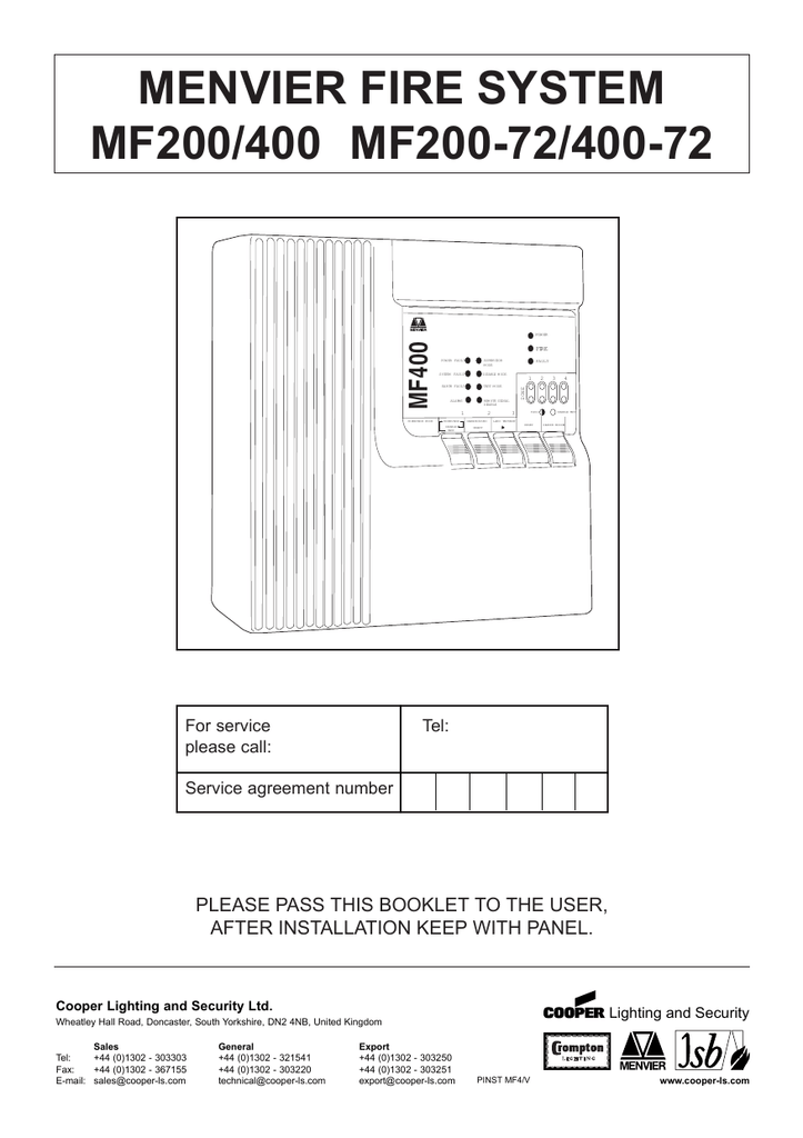
Cooper conventional detectors can be connected via a zone monitor unit or shop unit. In the range there are two main options either the flexible easily switchable 5 in 1 detector that brings together all the detection mode or the straightforward single detection mode range.
Smoke Detector Circuit Basics
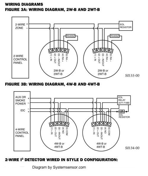
Cooper smoke detector wiring diagram. The smoke detectors wiring harness has two parts. How to install a hardwired smoke alarm ac power and alarm wiring intended for how to wire smoke detectors in series diagram image size 715 x 365 px. White black and yellow. You should be able to see three wires coming out of the harness. Truly we have been realized that how to wire smoke detectors in series diagram is being just about the most popular topic at this time. Variety of smoke detector wiring diagram.
It shows the parts of the circuit as simplified forms and the power and also signal links in between the tools. Know the basics of smoke detector wiring and learn how these detectors are connected together in a series. Both options include optical photo thermal and heat modes. For 4 wire smoke detector wiring running an extra 4 conductor wire gives the same effect. Cooper smoke detector wiring diagram wiring diagram is a simplified standard pictorial representation of an electrical circuit. This includes detectors call points and all other addressable items eg.
Two type of fire alarm detection system 1 addressable system 2conventional system modernexpe. Eaton has a large range of detectors for conventional fire alarm systems designed to meet the demands of nearly any application. A wiring diagram is a simplified standard photographic representation of an electrical circuit. Cap320 optical smoke detector 101 dia x 33d. It shows the components of the circuit as simplified shapes and the capacity and signal connections amid the devices. The extra run of 4 conductor wire gives us a return path to the panel.
The fixed wires and the wires that protrude from the harness. For details on how to do this see connecting 4 wire smoke detectors. Basic electricians pouch of hand tools non metal step ladder and a voltage tester. Cable and wiring 19 installation 20 fixing details 21 external connections 22 networking 23 inputsoutputs 24. Mpu mio loop repeaters etc when designing systems its recommended that allowances are made for future expansion short circuit isolators are incorporated into every r6000 loop device including smoke detectors heat detectors sounders callpoints and interfaces. This allows you to locate the end of line resistor and power supervision relay at the alarm panel.
Wiring smoke detectors electrical project skill level. Here i show the layout diagram of fire alarm detection system.
