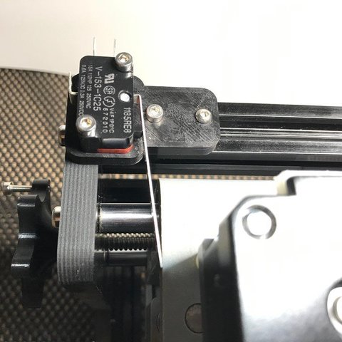
This thing will help you install limit switches which help prevent damaging the machine by crashing it. The platform will crash when it tries to go back because the wires and wire ties are in the way.

Dn 8040 Wiring Diagram Cnc Limit Switch Wiring Diagram Limit
Cnc 3018 limit switch wiring diagram. The cnc router from china commonly referred to as 3018 pro cnc router is fairly inexpensive and can be upgraded fairly easily. Go to the new parallel breakout board to get more information and the wiring diagram. You will know this because the movement buttons will be greyed out. Wiring limit switches the limit switches are used to detect the physical limits of the working area and to position the head in initial position during the homing process. This is how a major website shows to wire the cnc 3018 pro. This is totally wrong.
The wiring of the parallel breakout board from the output terminals to the driver digital pulse step pulse and direction lines are explained. Wiring harnesses that were supplied with the switches have three wires two of which we are using. Properly connected limit switches can significantly increase the reliability of the grbl the microcontroller pins connected to the switches are very vulnerable to any noise. Precision node cnc 3018 pro end stop node switch testing and limit switchhoming configuration. Use one of the extra wires we ran through the dragchain in the previous step to connect this limit switch to the main board. So far i havewiring diagrams for the laser power supply will be mostly the same with the updated power supply.
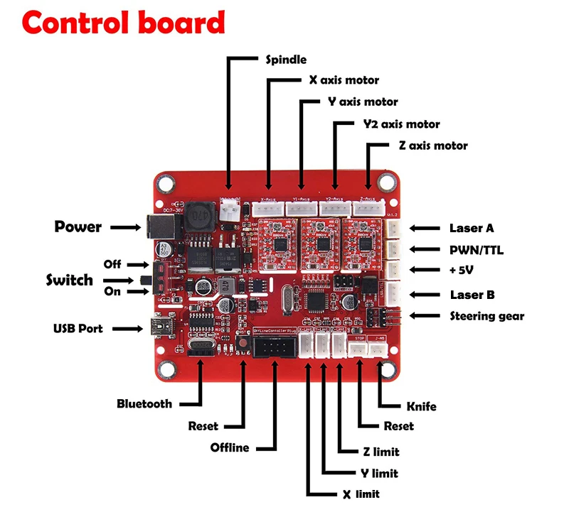
The standard version is mostly made of. The green wire is the common of the switch and the black is the normally open contact. The z axis switch is simply screwed into the z axis mount. Plug them into the pcb according to the wiring diagram. Solder a red and black wire to the limit switch and add dupont connectors to the other end. It is required as the z axis is tested first.
The new parallel breakout board appears a bit different but the process of wiring and testing is the same. Grbl arduino cnc wiring limit switches he limit switches are used to detect the physical limits of the working area and to position the head in initial position during the homing process. To resume using the cnc again you need to do to things a reset and b unlock. This is the z axis limit switch. This thing is intended to be used with the pro version which is made of both extruded aluminum and cnc routed plastic parts. Maker solutions 7896 views.
Therefore each limit switch black 3 pin connector plugs into the header with the green wire to the upper pin and the black wire to the lower pin. Once a limit switch is triggered the spindle is automatically stopped and the woodpecker board goes into a locked state to prevent any damage from occuring.
Gallery of Cnc 3018 Limit Switch Wiring Diagram