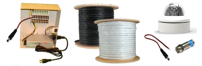
Cctv systems have many components with a variety of functions features and specifications. It shows the elements of the circuit as simplified forms and also the power and also signal links between the gadgets.
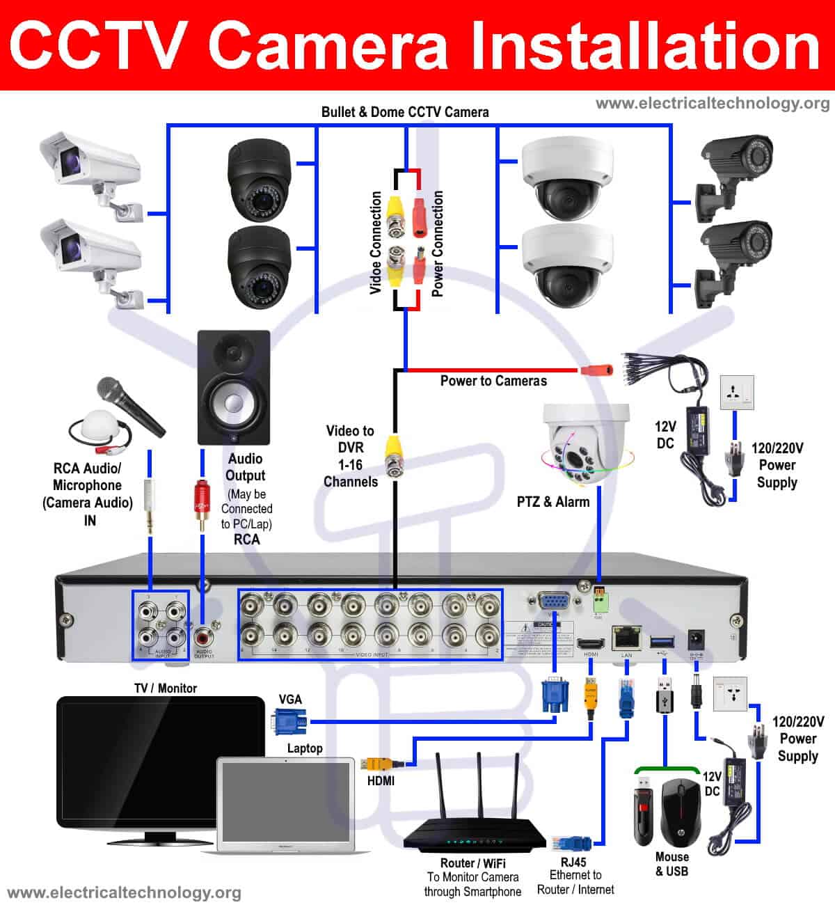
Cctv Camera Installation Step By Step Procedure With Dvr Setup
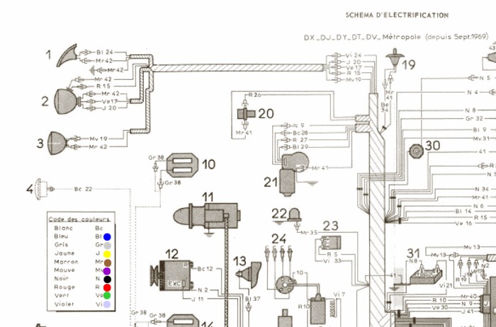
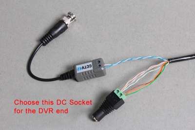
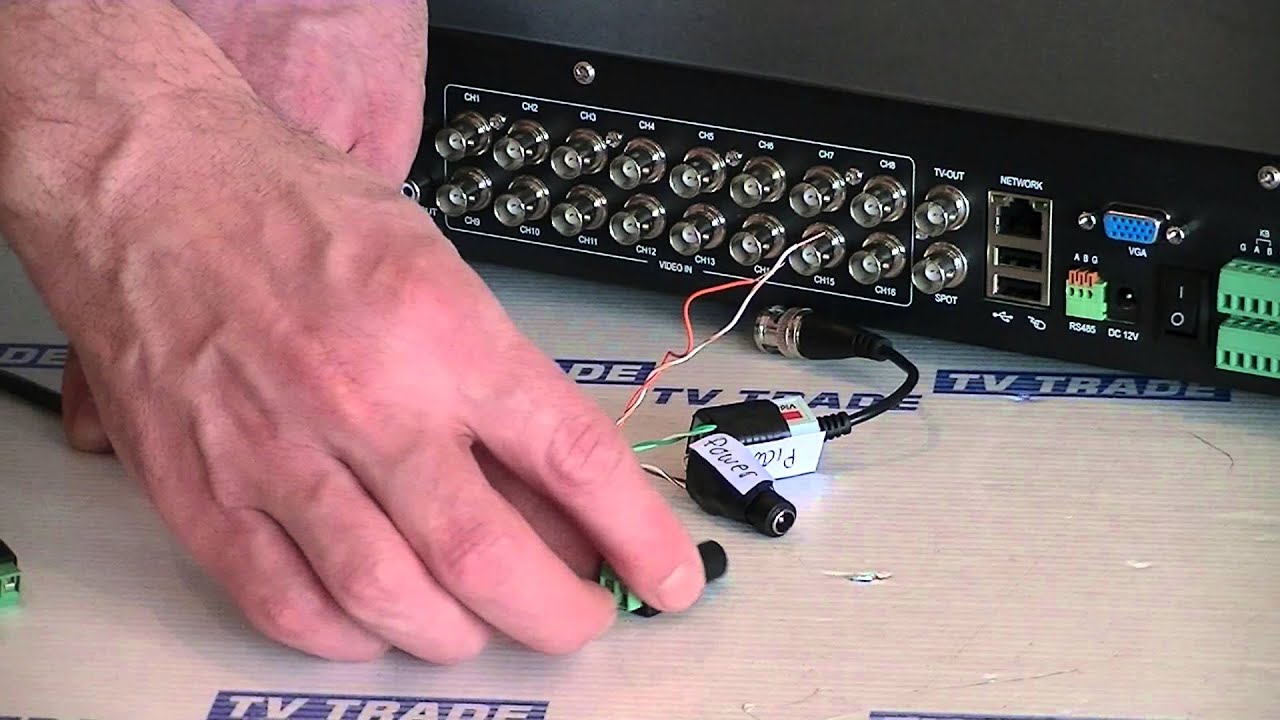
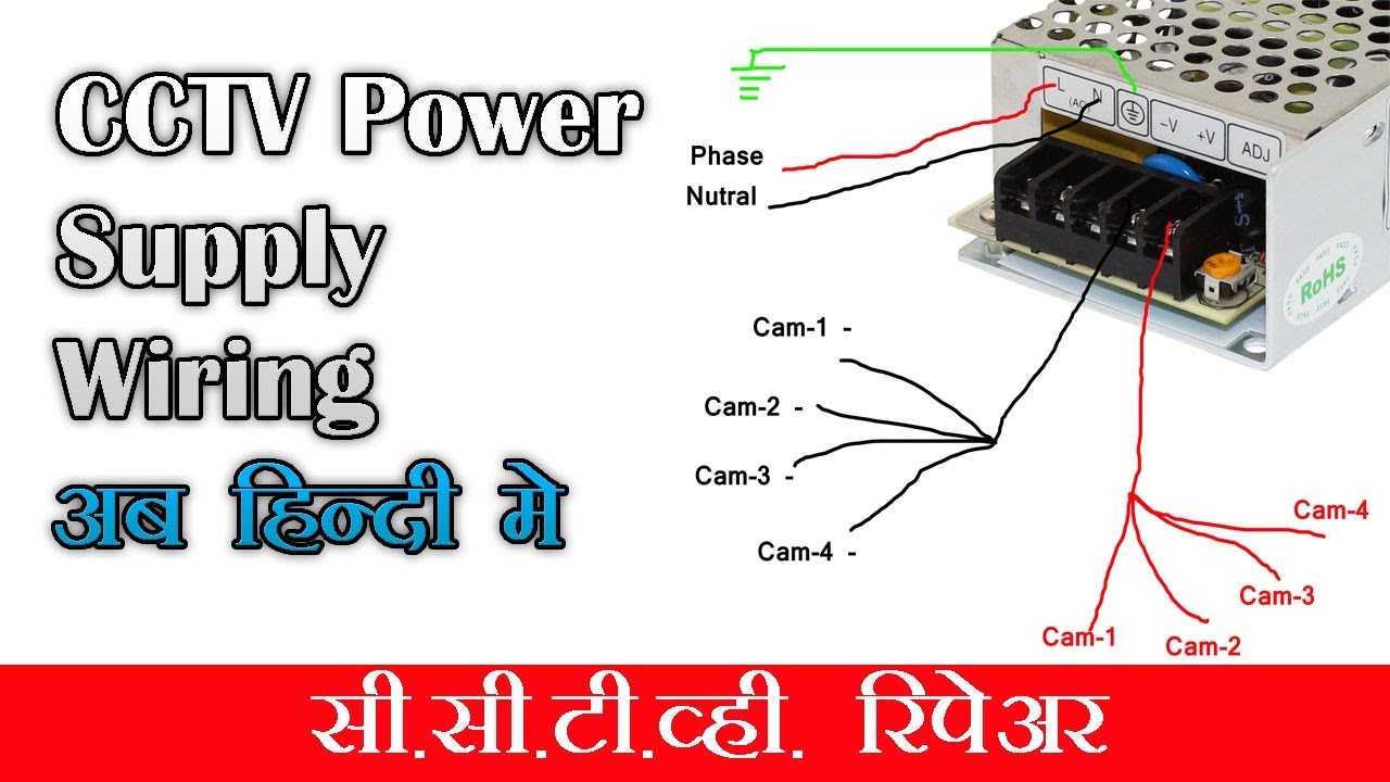
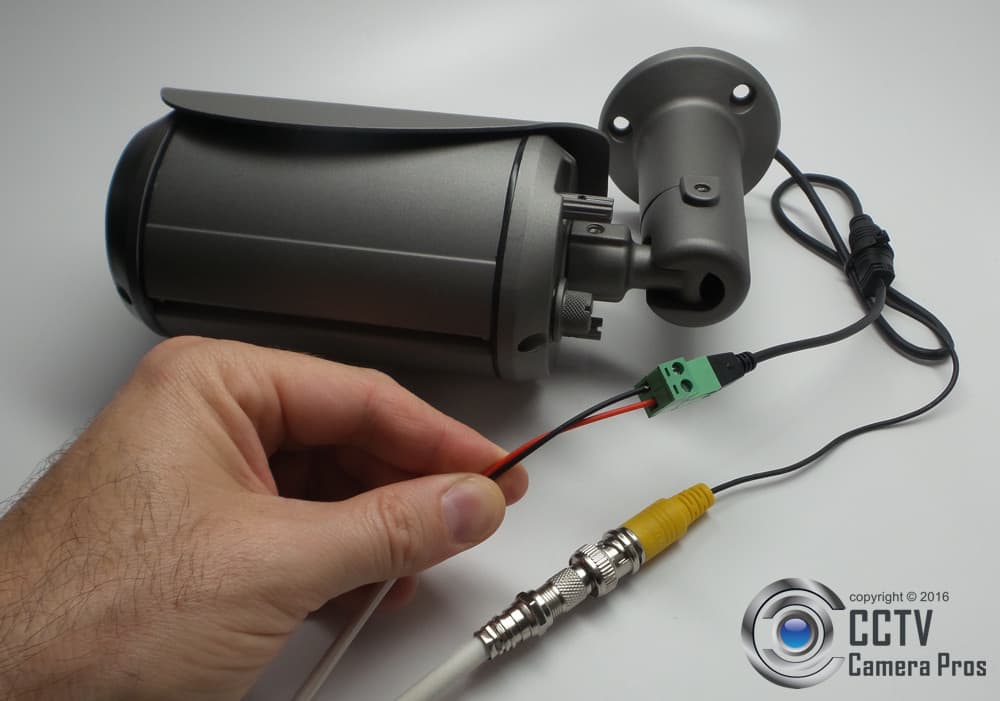
Cctv wiring diagram connection pdf. Collection of cctv camera wiring diagram. A wiring diagram is a streamlined traditional pictorial depiction of an electric circuit. Red is a power lead and the yellow is for the video transmission. Image from thermal camera 12. Sample block diagram notes. The camera should have two wires at its rear.
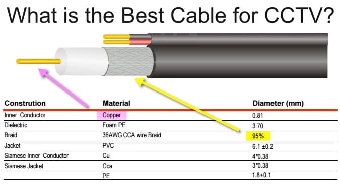
Cctv composite cable consists of rg59 two shielded twisted pairs power conductors 3. Only one blue white pair is used for telephone connection. Hard wired connection systems of the past. Color reference chart 12 figure 3 3. Cctv system can provide the means to assess an alarm generated by an intrusion detection. Attach the 4 cable multiplexer to the power supply.
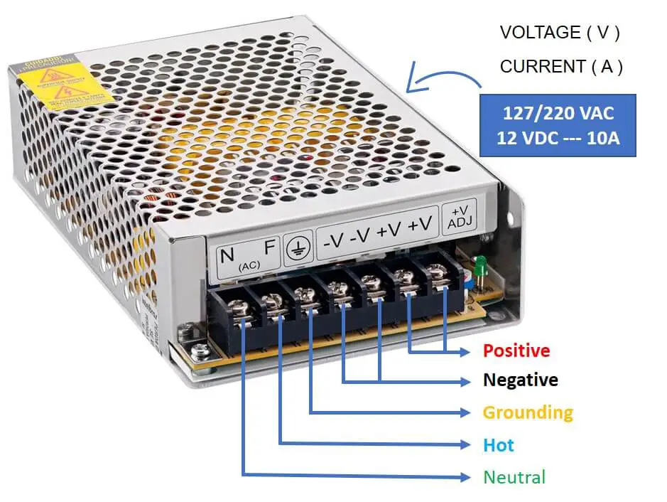
See cabinet wiring diagrams for details. A very first check out a circuit layout may be confusing yet if you could check out a metro map you could review schematics. Connect these two leads. Cctv camera wiring diagram a newbie s overview of circuit diagrams. Wiring the cameras correctly is vital in making sure that your cctv kit functions effectively. All the others are not connected.
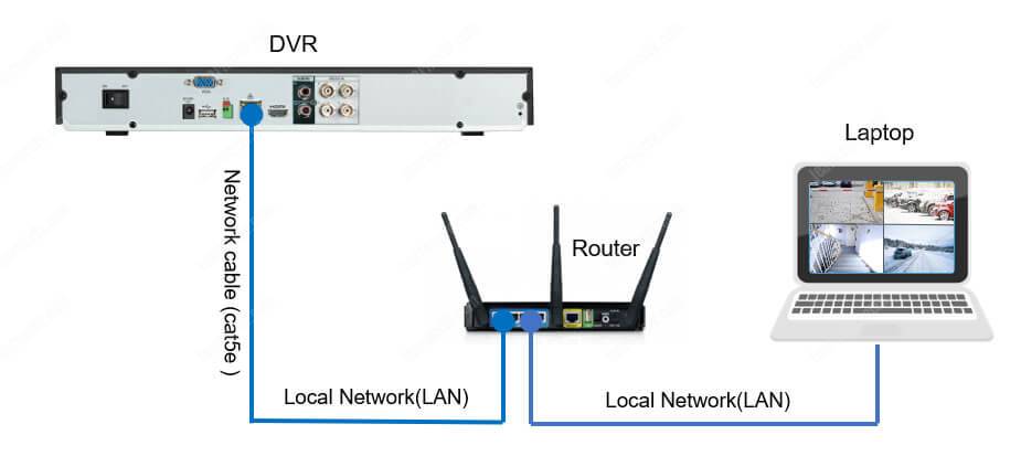
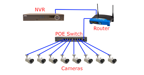
Standard cctv wiring diagram this is a diagram describing how any analog or hd analog system gets connected. Firstly we will look at the cameras. Block diagram presents a proposed system solution. Cctv component diagram example 9 figure 3 2.
Gallery of Cctv Wiring Diagram Connection Pdf