8272004 95947 pm. Rt3 v blade manifold wiring diagram 20.

F Superduty Boss Plow Install
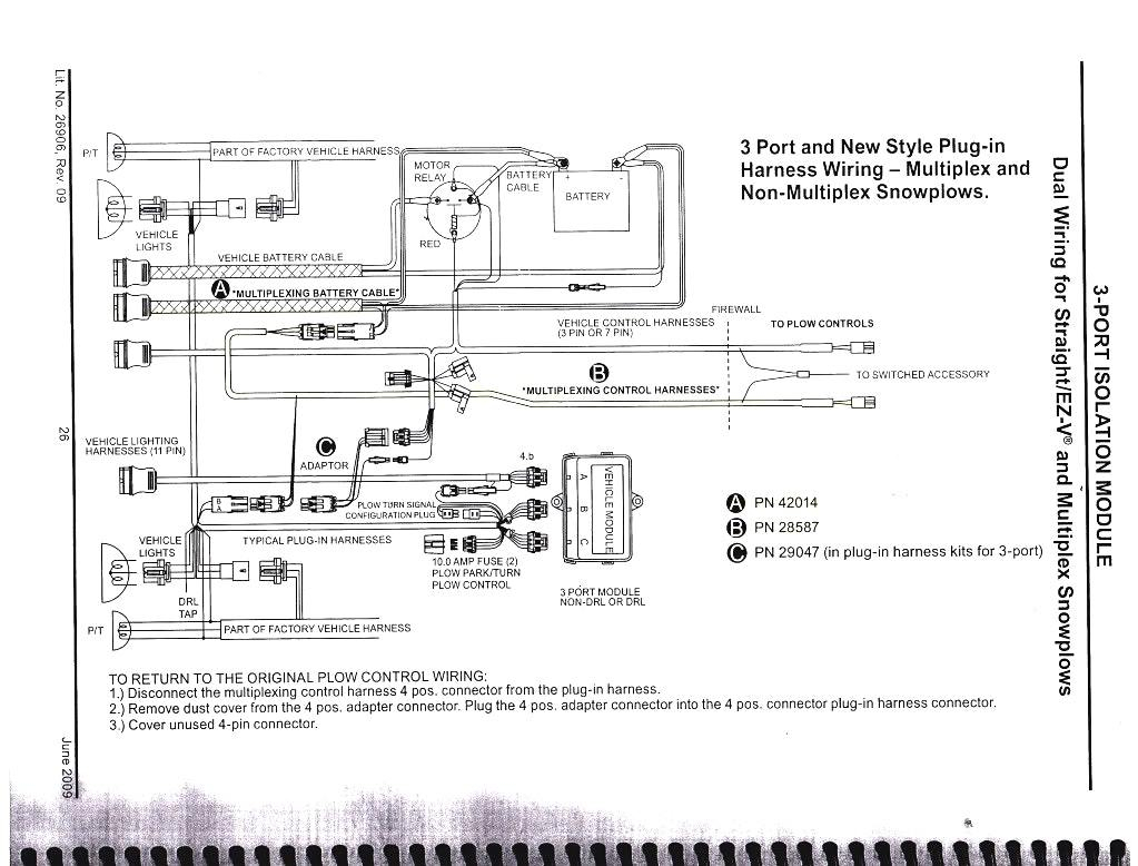
Boss v plow wiring diagram. A wiring diagram is a simplified standard photographic depiction of an electrical circuit. Recommended vehicle models refer to the boss snowplow application chart and selection guide. To ensure that it gives you the same high performance year after year. Electrical system wiring schematic plow side g10271. Wiring diagram smartlight2 wiring schematic smartlight2 control plug pin functions. Electrical system wiring schematic truck side electrical system wiring schematic truck side g10272.
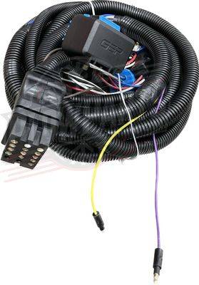
Your boss snowplow is designed for heavy duty rugged service with minimal maintenance. 11 rt3 power v blade with smarthitch wiring schematic figure 6. Vehicles equipped with air bags are designed such that the air bags will be activated in a frontal collision equivalent to hitting a solid barrier such as a wall at approximately 14 mph or more or. Collection of boss v plow wiring diagram. The power v dxt harness wiring is the best option for those looking for the boss repair parts for their 8 ft 2 inch or 9 ft 2 inch smarthitch 2 power v dxt snowplow from iteparts. Microsoft word 13 pin wiring schematicdoc author.
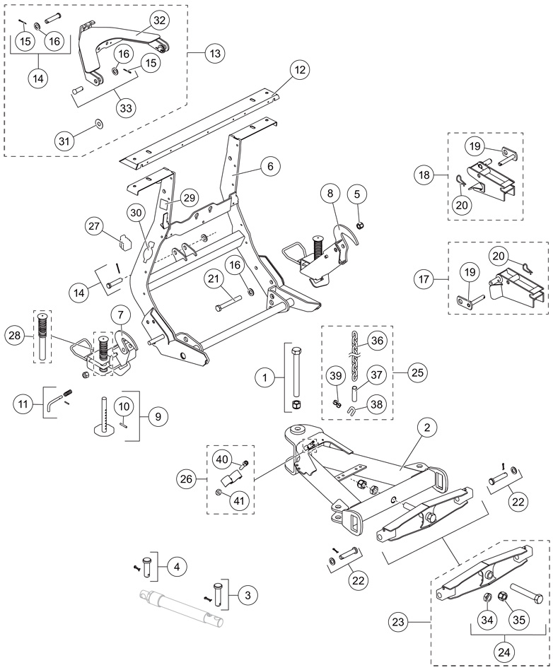
A wiring diagram normally gives info regarding the relative placement and plan of gadgets as well as terminals on the gadgets to assist in structure or servicing the device. Snowplow parts and diagrams. It shows the elements of the circuit as streamlined forms as well as the power and signal links between the devices. Rt3 power v blade with smarthitch wiring diagram figure 5. Rt3 wiring schematic.


