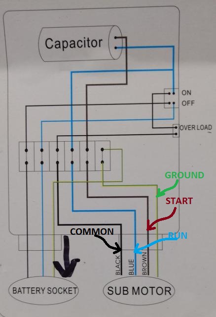
Submersible pump control box wiring diagram submersible well pump wiring diagram. Click on the image to enlarge and then save it to your computer by right clicking on the image.

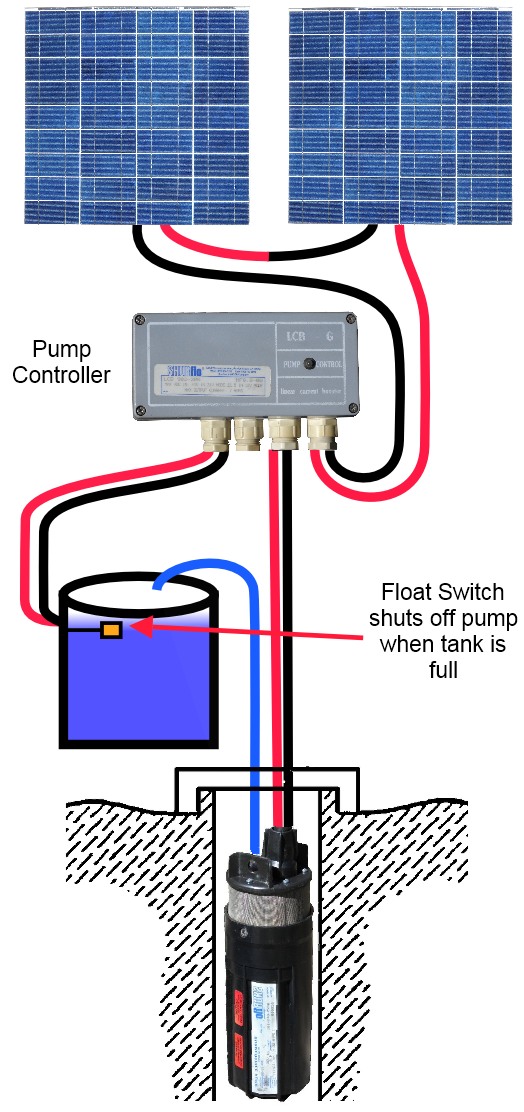
Float Switch Installation Wiring Amp Control Diagrams Apg
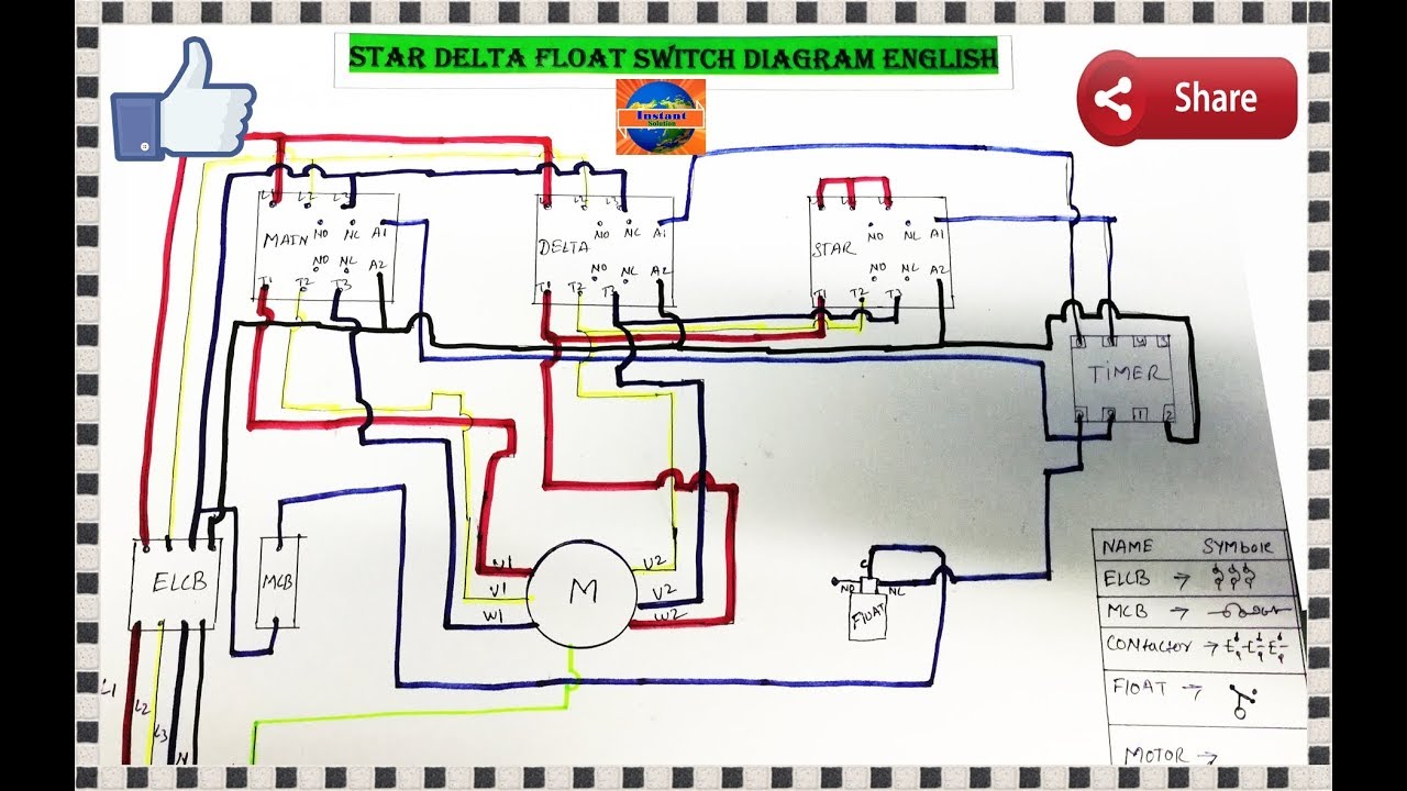
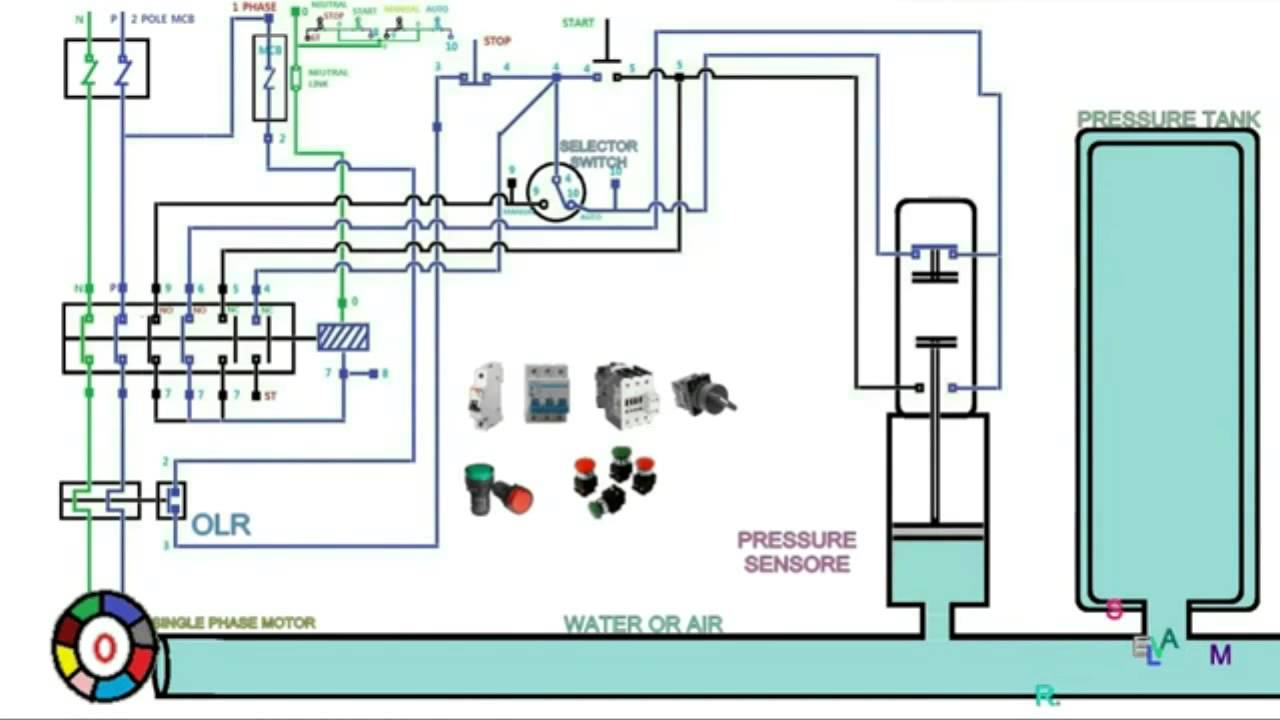
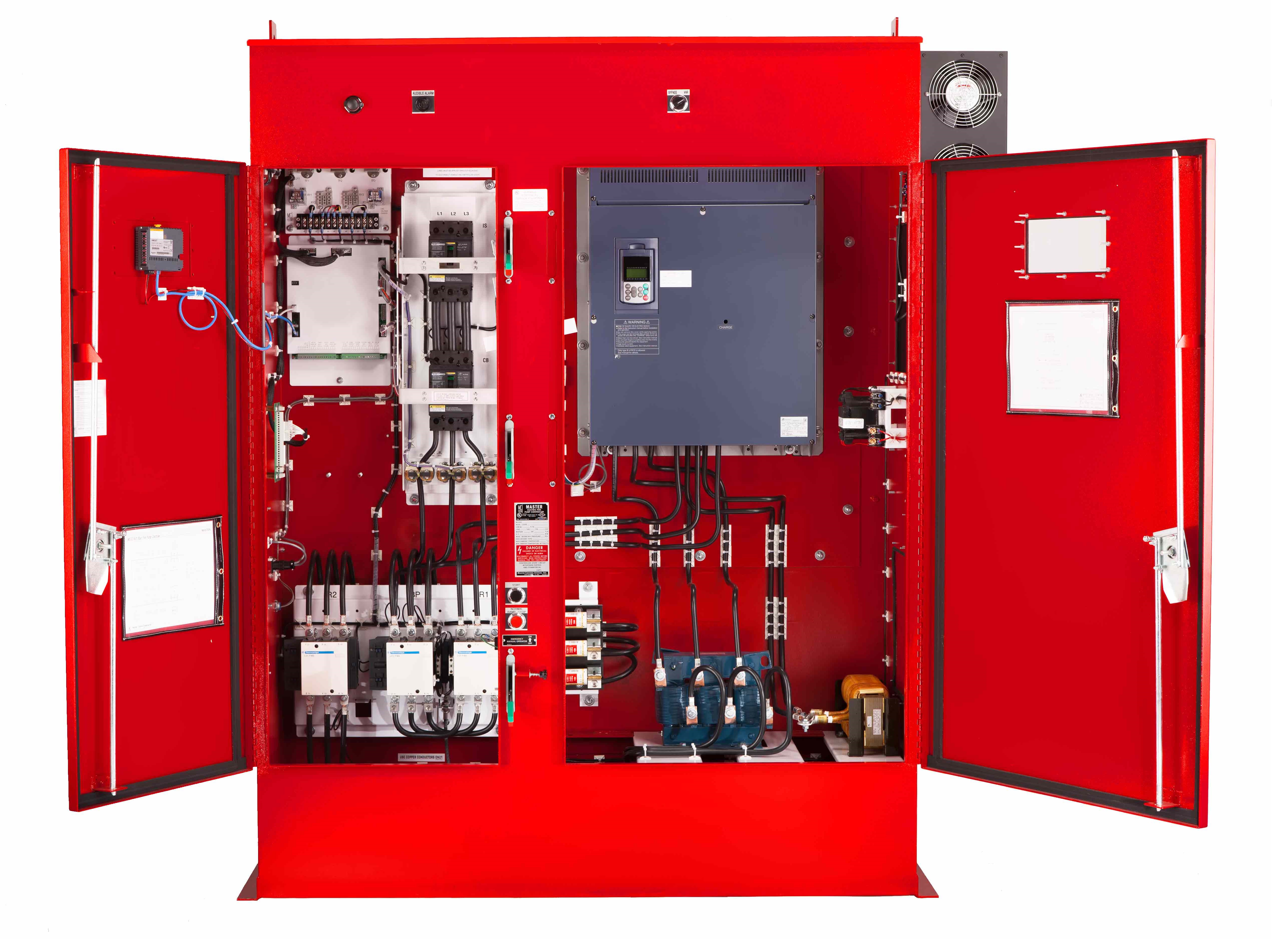
Booster pump control panel wiring diagram. A wiring diagram is a simplified conventional photographic representation of an electrical circuit. Click on the image to enlarge and then save it to your computer by right clicking on the image. Booster pump panel troubleshoot. It reveals the parts of the circuit as streamlined shapes and the power and also signal links in between the devices. The pumps are operated in a leadlaglag2 mode with the turn on and turn off points for each pump individually setable from the front panel. Three phase dol starter control overload indicator power wiring diagram duration.
Thank you for watching guys. Assortment of submersible pump control box wiring diagram. Motor control panel fully automatic pump contr. Variety of pump control panel wiring diagram schematic. Pump control box wiring diagram get free image about wiring diagram diesel engine fire pump controller wiring diagram new diesel duplex pump control panel wiring diagram awesome nih standard. Httpsyoutubencxdq9agphk stop start control wiring and diagram.
A built in pump alternator can be enabled or disabled from the front panel. Please do check the link for magnetic contactor check up video. Assortment of grundfos pump wiring diagram. 311 pump control the cpc 3 is designed to control up to three pumps using three 15 a mp relays. Single phase wiring diagrams single phase wiring diagram for 05hp pumps with governor switch single phase wiring diagram with governor switch single phase wiring diagram without governor switch three phase wiring diagrams three phase 208v wiring diagram three phase 230v wiring diagram three phase 460v wiring diagram three phase 575v wiring diagram kb pump wiring diagrams kb pump 230v wiring.
Gallery of Booster Pump Control Panel Wiring Diagram