A very first look at a circuit representation could be complex yet if you can read a train. January 13 2019 by larry a.

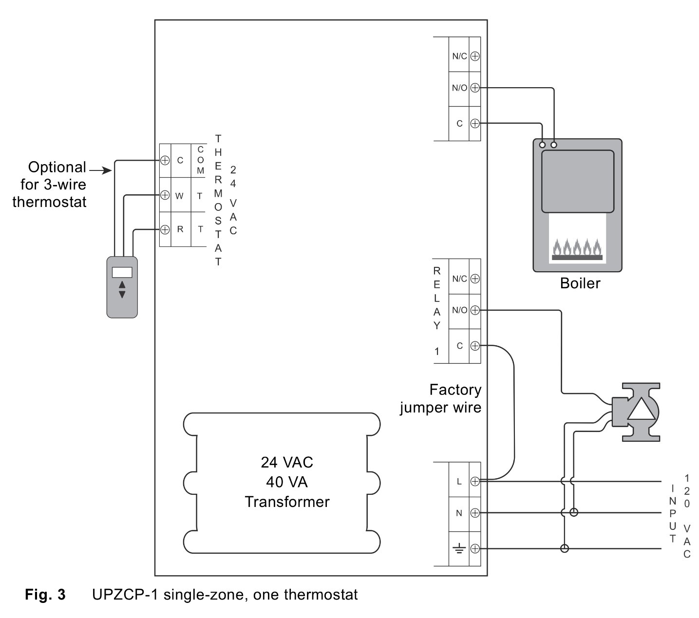
Installation Diagrams Thermostat Wiring Boiler
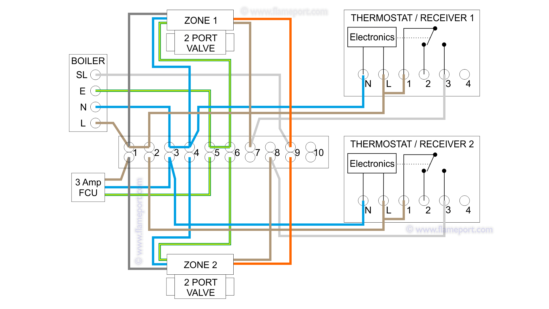
Boiler thermostat wiring diagram. A wiring diagram is a simplified conventional photographic depiction of an electrical circuit. Collection of boiler wiring diagram for thermostat. The boiler thermostat is one of the most important devices in the home yet it is often overlooked. R the r terminal is the power. It is a red wire and comes from the transformer usually located in the air handler for split systems but you may find the transformer in the condensing unit. Central boiler thermostat wiring diagram sample house thermostat wiring diagram download wiring diagram for s plan central heating system 2017 hive nest wireless thermostat wiring diagram new wiring diagram for a a novice s overview of circuit diagrams.
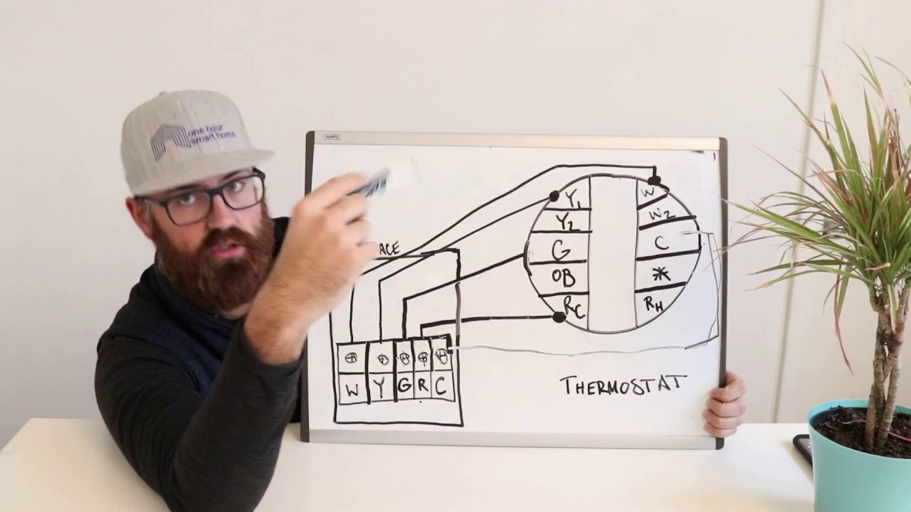
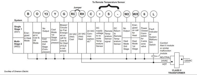
Thermostat wiring and wire color chart thermostat wiring colors code. It reveals the parts of the circuit as simplified shapes and also the power and also signal connections between the gadgets. This relatively small device is responsible for controlling the level of heat in your home during the cooler months. Terminal r or terminal rh for the red wire. Therefore you will use the following color code for simple thermostat wiring. In the past boiler thermostat wiring used to be rated for 110 volts but now modern systems are rated for 24 volts.
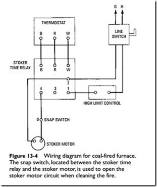
These application drawings include detailed wiring diagrams and set up details allowing installers to fully utilize the capability and. Thermostat wiring diagrams furnaces heating only thermostat wiring diagrams if you only have a furnace such as a gas furnace oil furnace electric furnace or a boiler. Color of wire and termination. Brand boilers can do more with less field wiring and fewer aftermarket controls and components improving the operation of both new and replacement boiler installations.
Gallery of Boiler Thermostat Wiring Diagram