Bldc motor controller wiring diagram gallery 2018 24v36v48v 250w350w bldc motor speed controller 6 mosfet dual. A brushless motor is constructed with a per manent magnet rotor and wire wound stator poles.

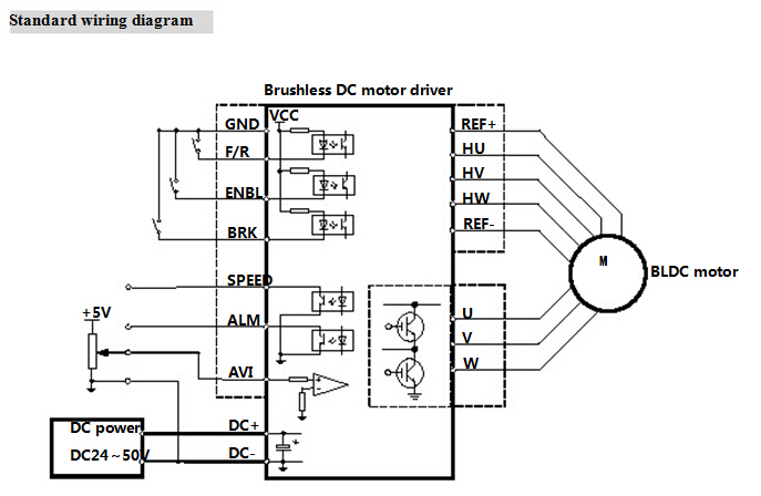
Da 3839 Pinout Application Circuits Brushless Dc Motor Drive
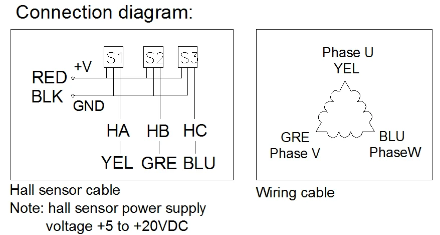
Bldc motor wiring diagram. It is made up of stacked steel laminations with axially cut slots for winding. Golden motor wiring diagram new brushless motors bldc mc brushless dc motor controller mc ncv 5 electrical characteristics vcc vc 20 v rt 4 7 k ct 10 nf ta 25c unless otherwise noted car engine diagram parts lovely exploded view ecx ruckus mt 1 10 2wd rtr brushless lipol. Bldc motors can come in one two or three phase. Return to the correct wiring diagram and connect the sensors to terminals s3 s2 and s1 of p1. The structure of the stator of a bldc motor is similar to that of an induction motor. It shows the elements of the circuit as simplified forms as well as the power as well as signal connections between the gadgets.
A stator and a rotor. Tp is the abbreviation for thermal protection. It shows the parts of the circuit as simplified forms and the power and also signal links in between the tools. A wiring diagram is a streamlined traditional photographic representation of an electric circuit. Collection of bldc motor controller wiring diagram. Sensored brushless dc bldc motor control with pic16f877a.
28 best brushless dc motor images on pinterest. Electrical energy is converted to mechanical energy by the magnetic attractive forces between the permanent magnet rotor and a rotating magnetic field induced in the wound stator poles. The type of thermal overload for which the thermal protection is designed 1 digit. Electric bike controller wiring diagram in addition electric motor. Different types of thermal protection exist and are identified by a tp code tpxxx which indicates. A wiring diagram is a streamlined standard pictorial representation of an electric circuit.
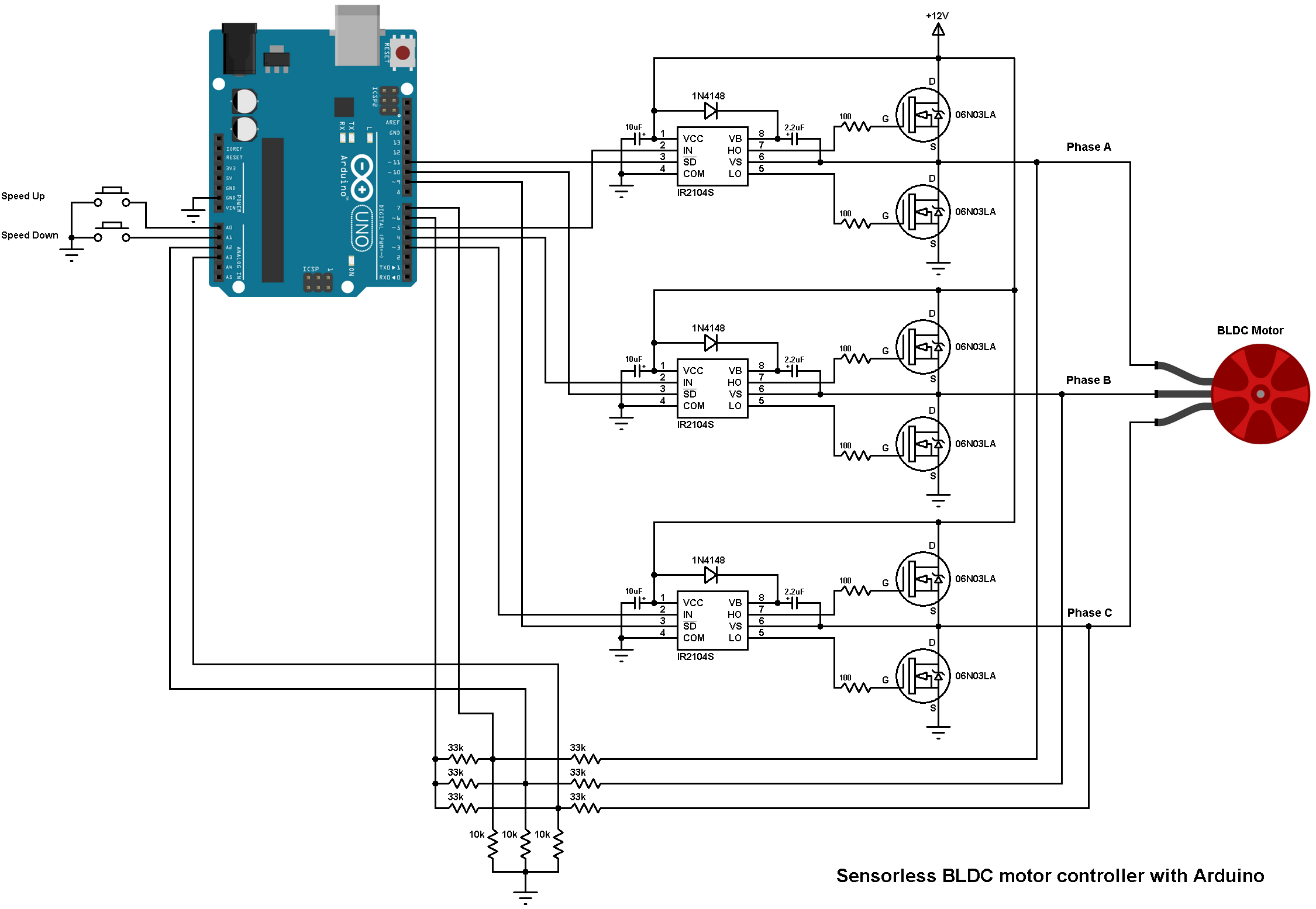
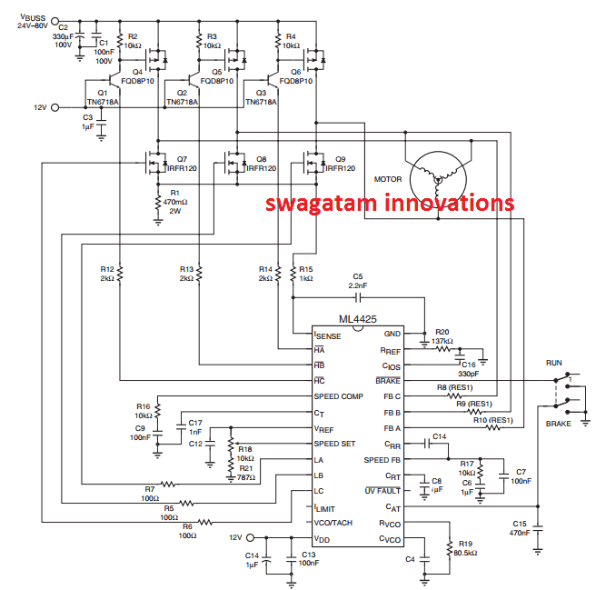
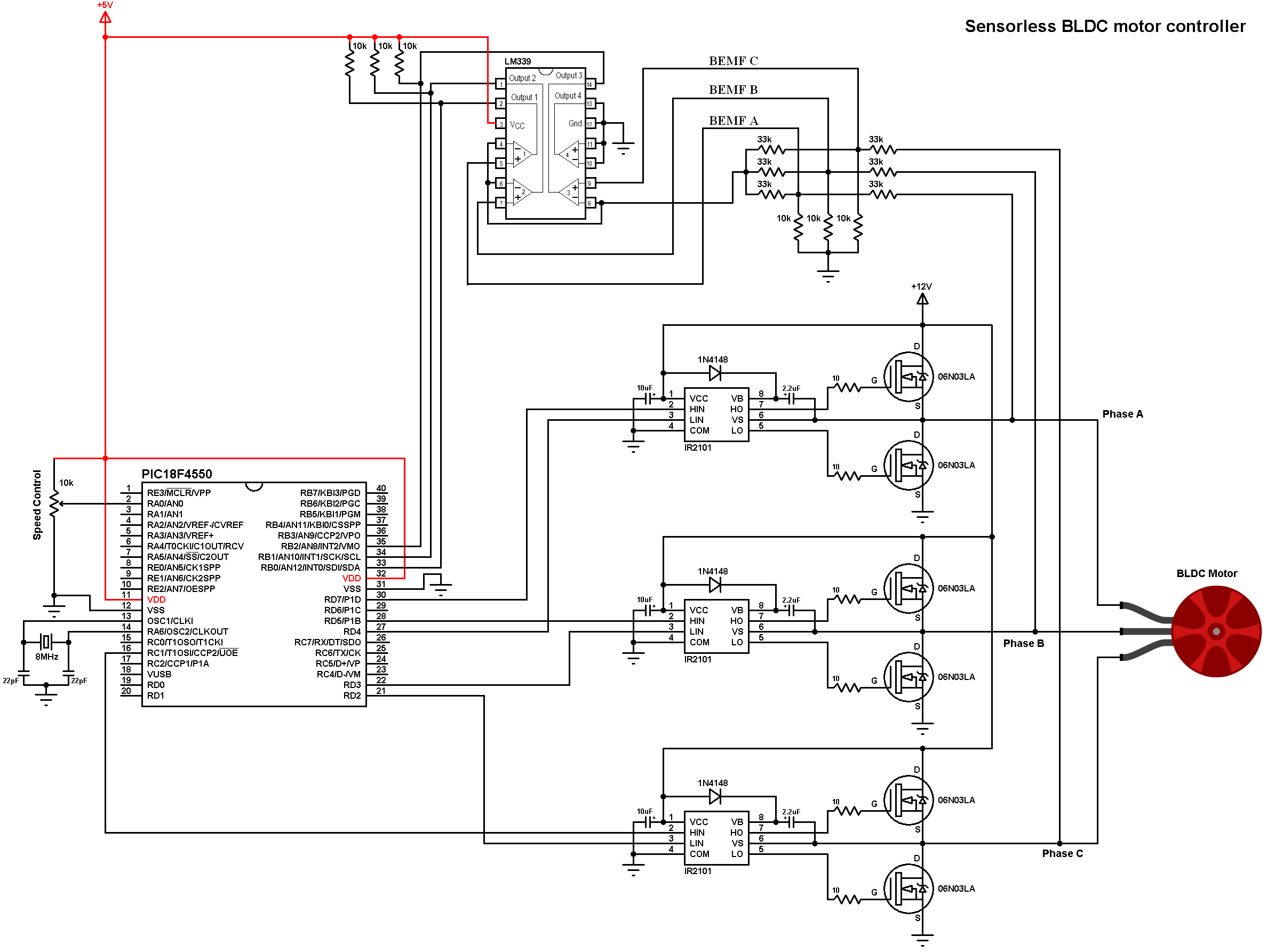
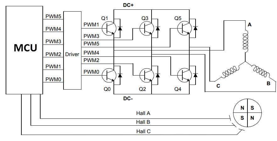
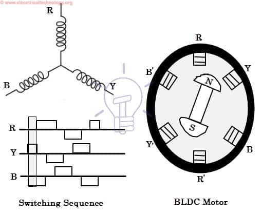
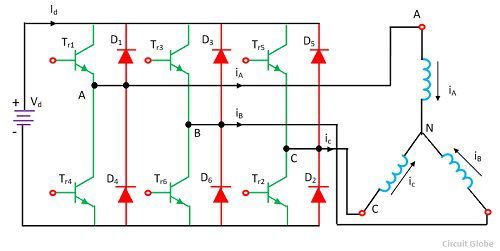
Here hall effect sensors are used for position and speed feedback. Three phase bldc motors are the most common and will be the subject of the rest of this article. The diagrams in as 190 show the sequencing of the hall sensor outputs as related to the motor phases. Because the rotating magnetic field generated by the stator causes the rotor to revolve at the same frequency a bldc motor is known as a synchronous type. The figure below shows the simple bldc motor drive circuit which consists of mosfet bridge also called as inverter bridge electronic controller hall effect sensor and bldc motor. Assortment of bldc motor controller wiring diagram.
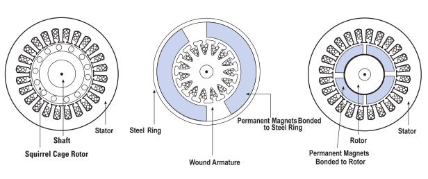
As you can see in the image a bldc motor consists of two main parts. Hook up procedure for groschopp bldc motors locate groschopp drawing as 190 motor connection diagram brushless dc motor. Figure 1 is a simplified illustration of bldc motor con struction. The following image shows the cross section of a bldc motor. The degree of protection that an internal protection device provides is classified in the iec 60034 11 standard.
Gallery of Bldc Motor Wiring Diagram

.png)