Collection of baldor single phase motor wiring diagram. The drawing for the product you have selected is available from our part community portal.

Hl 3841 Wiring Diagram Moreover Baldor Single Phase Motor
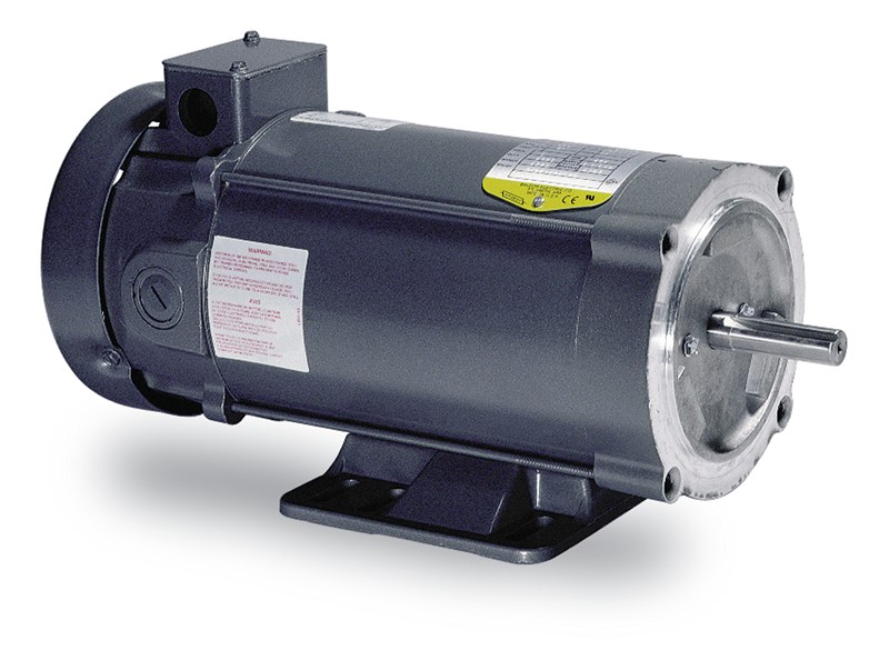
Baldor super e motor wiring diagram. The wiring fusing and grounding must comply with the national electrical code and local codes. The tefc enclosure protects the motor from harsh environments because air does. The department of energy estimates that wiring a baldor motor can at first glance look to be a very intimidating task. Categorycustomcapabilities click here for information on custom solutions. Dont see what youre looking for. A horsepower baldor super e motor can save more than per year during continuous use.
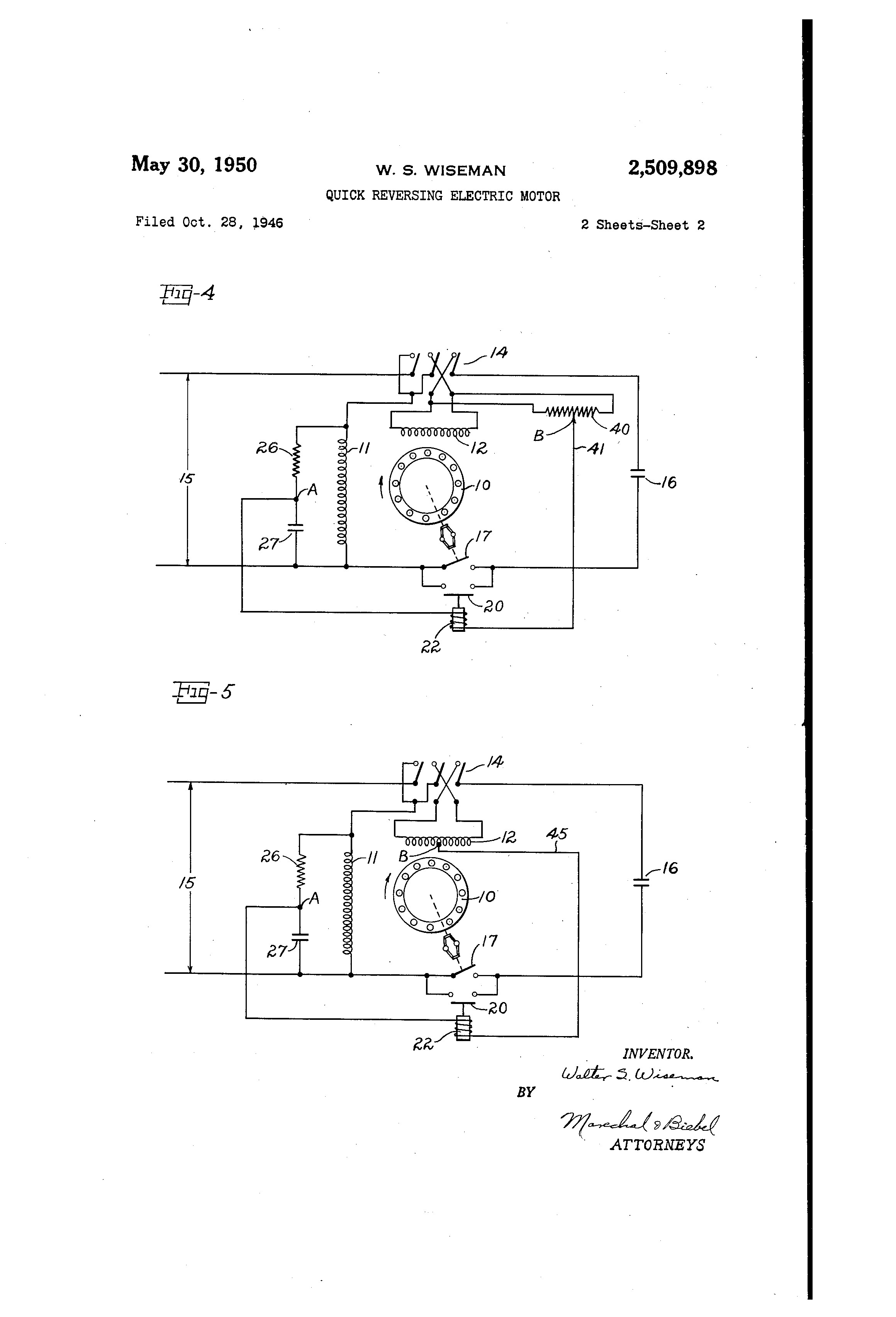
It shows the elements of the circuit as streamlined shapes as well as the power and signal links in between the tools. Modest efficiency ratings yield substantial energy savings. Refer to mn408 for additional details on lead marking. Doe recommends applications and processing improvements. If this motor is installed as part of a motor control drive system connect and protect the motor according to the control manufacturers diagrams. Payback varies depending on motor use.
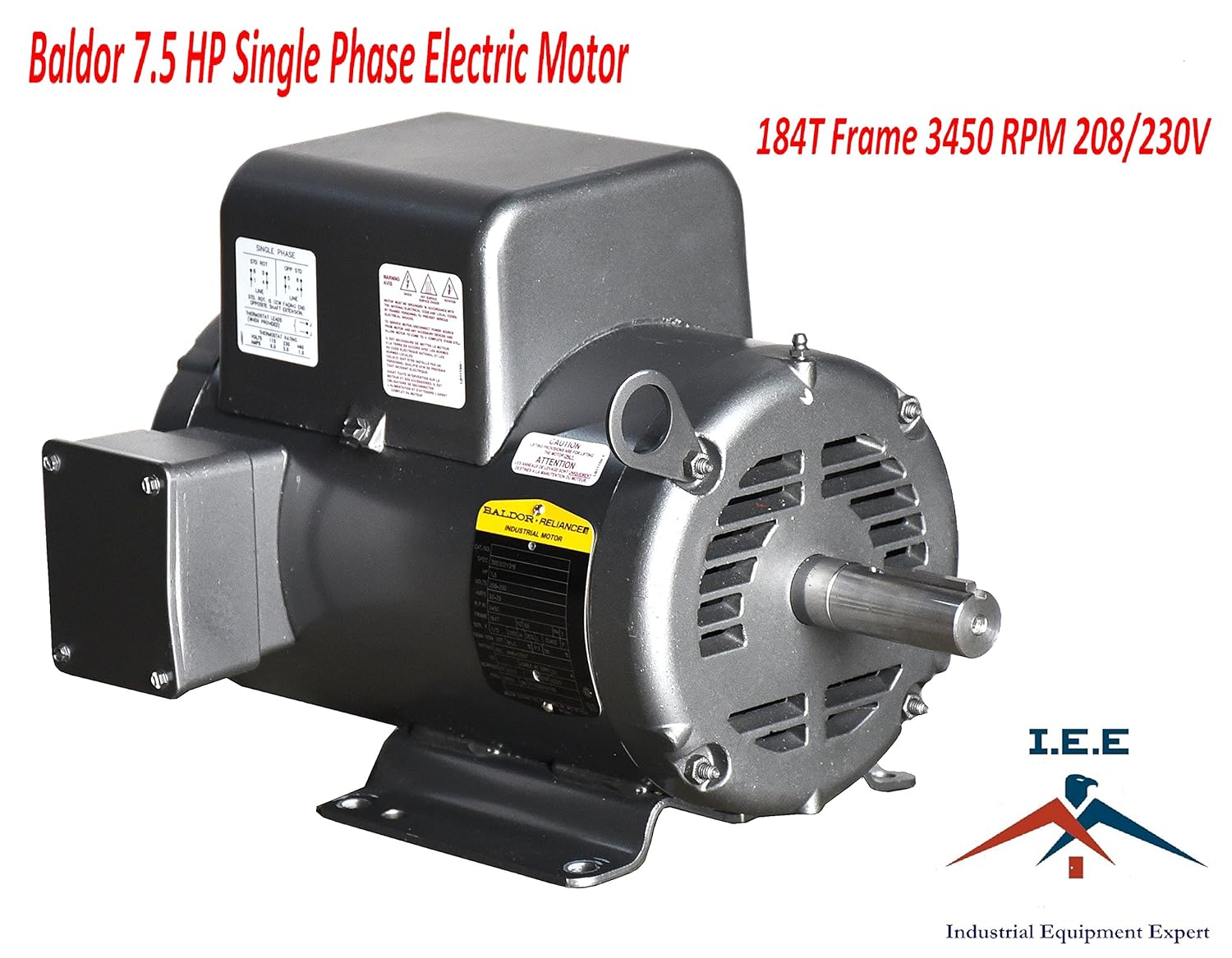
Baldorreliance super e tefc motors meet or exceed nema premium efficiency in your choice of steel band or cast iron frame ideal for tough industrial applications. Wiring connect the motor as shown in the connection diagrams. Super e motor industrial electric motors represent the single largest end use of electricity in the united states. Visit our portal by following the link below. Payback can occur in less than a year depending on motor size. The right combination of baldor super e motors and adjustable speed drives can yield savings up to 50 percent.
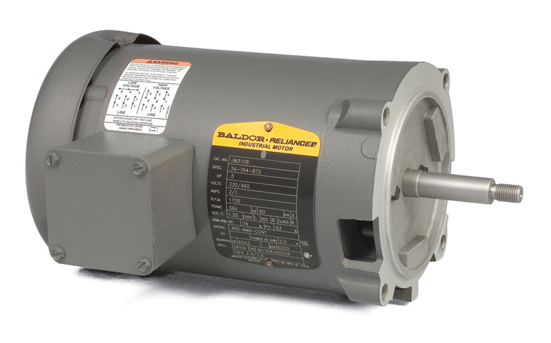
Baldor produces a wide range of alternating current ac and direct current dc electric motors in 26 plants world wide. When the motor is connected to the load for proper direction of rotation and started it should start quickly and run smoothly. Each type of baldor electric motor has labeled wiring diagrams on a plate fixed on the motor. A wiring diagram is a streamlined traditional photographic depiction of an electrical circuit. Wiring connect the motor as shown in the connection diagram. For additional service please contact a local sales office.
The wiring fusing and grounding must comply with the national electrical code. If not stop the motor immediately and determine the cause.
Gallery of Baldor Super E Motor Wiring Diagram