A wiring diagram is frequently used to repair troubles as well as to earn sure that the connections have been made which every little thing is existing. Automatic transfer switch ats022.
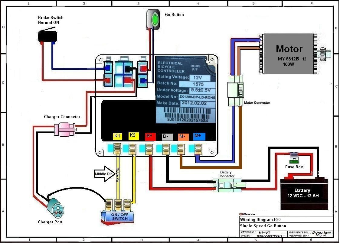
Ae1 Razor Electric Scooter Wiring Diagram Trikke E2 Wiring
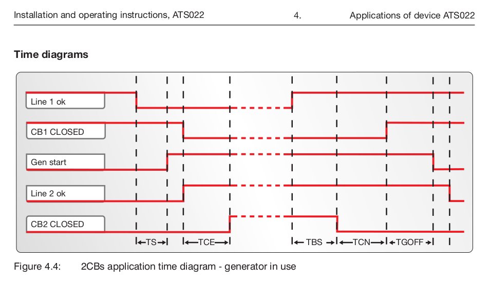
Ats022 wiring diagram. The motorized change over switches have snap on control wire connections. The new generation of the ats family ats021 and ats022 offers the most advanced and comprehensive power continuity solution. Applications of device ats022. Graphic display is also provided for ats022. Abb presents the new generation of automatic transfer switches the result of worldwide experience in low voltage applications. In cases where the normal emergency and.
Applications ats family is highly suited to use in all emergency power sup ply systems where a ready to install easy to use and reliable solution is required. All cable lug connections must be tightened to the proper torque values as shown intable 2. For more details refer to the wiring diagrams of the product. Ats022 is equipped with a communication unit which allows the integration with supervision systems via modbus rs485. The 16 to 125 ampere sizes can be snapped on to a din rail and the front fits in the 45 mm consumer unit cut out. Configuring the unit without a priority line or with ln2 as the priority line does not change the way changeover of cb3 is managed.
Oxides from cables by cleaning with a wire brush. Do not run cables or wiring behind front connected transfer switches. The sizes t4 and t5 in the plug in version and t4 t5 t6 and t7 in the withdrawable one as well. The npl loads are always combined with line ln1. A pictorial diagram would certainly show extra information of the physical appearance whereas a wiring diagram utilizes a more symbolic notation to emphasize affiliations over physical look. Use of modbus rs485 communication use in systems with 16 23hz rated frequency use in single phase systems with un 575 to 109vac a 24vdc to 110vdc 10 15 emergency power supply can be used.
Tmax t family is available as a complete range of moulded case circuit breakers up to 1600 a. With ats022 the auxiliary supply is only required in the following cases. Ex wiring diagram ats 022 for t5 normal r s t n n t s r generator k2 k1 k1 k2 k2 k1 k2 k1 c11 a1 u1 ac11 1 u1 95 u2 u2 96 13 95 96 ne n 13 14 14 n e start gen. Ats022 autotranswitch advanced control abb1sda065524r1. Auxiliary contacts can be snapped on to the sides of the switches and the power terminals can be connected in parallel with bridging bars. Verify that all connections are cor rect before tightening the lugs.
All the circuit breakers both three pole and four pole are available in the fixed version.
Gallery of Ats022 Wiring Diagram