Wire the if16 module. Power supply that matches the input transmitter specifications.
Wiring Confusion Do More And Allen Bradley Analogue Input In
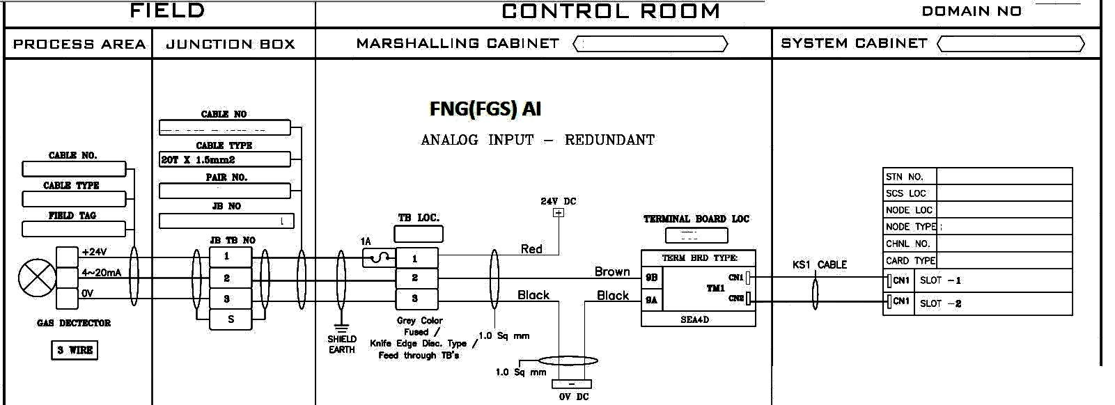
Analog input card wiring diagram. Wire fragments that. A b if16 analog card. Wiring up 31 wiring and block diagram analog input module ai 8xi 2 4 wire ba 6es7134 6gf00 0aa1 manual 032015 a5e34941201 aa 11 connection. Tbch or tbs6h wiring diagram single ended voltage dwg. Connect only one end of the cable shield to earth ground. The following analog inputoutput modules are european zone 2 approved.
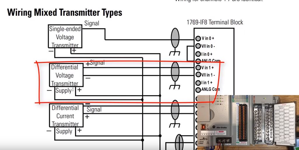
Differential analog inputs are more immune to noise than single ended analog inputs. When talking about 2 3 and 4 wires what were talking about here is really the transmitters or transducers. Wiring differential inputs attention be careful when stripping wires. The analog input module is an intelligent block transfer module that interfaces analog input signals with any allen bradley programmable controllers that have block transfer capability. Separate power source when wiring various modules updated diagram labels for wiring the 1756 if6i module chapter 6 updated fahrenheit temperature conversion range values for cold junction compensation types and cold junction offset option added advisory not to exceed the spec ific isolation voltage when using a. Note that these diagrams are without a barrier or isolator fuses and surge protector for keeping it very simple and understandable.
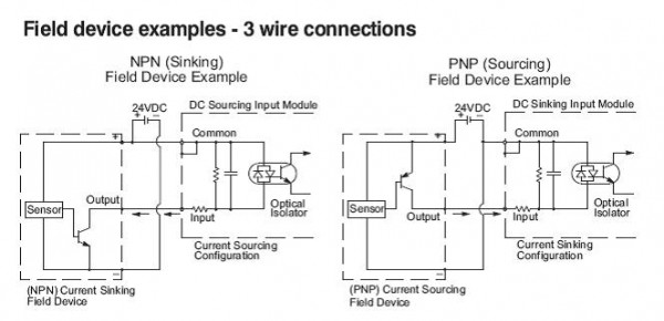
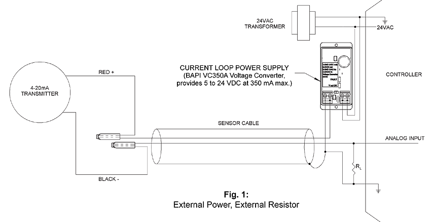
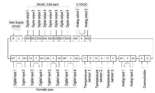
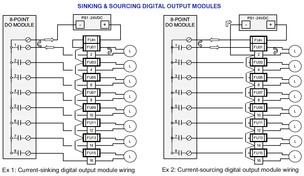
Analog input module ai 8xuirtdtc st 6es75317kf00 0ab0 manual 072014 a5e03484864 ac 9 properties the module has the following technical properties. With that background in mind lets take a look at the wiring of current analog inputs. In this article we are sharing the basic concepts of plc and dcs control systems wiring diagrams for digital input di digital output do analog input ai and analog output ao signals. Block transfer programming moves input data words from the modules memory to a designated area in the processor data table in a single scan. Chapter 4 non isolated analog voltagecurrent input modules if16 if8. Current and voltage wiring examples for the.
Use shielded communication cable belden 8761 and keep length as short as possible. Connecting wiring for the analog inputs and outputs. Current measurement 2 wire connection the following figure shows the block diagram and an example for the terminal assignment of the analog input module ai 8xi 2 4 wire ba on the baseunit bu type. Slc 500 analog input module 11 publication 1746 in006a us p wiring single ended inputs the following diagram shows typical wiring for the 1746 ni8 module. They can generally be divided in three types. 1794 ie8b 1794 ie8kb 1794 oe4b 1794 oe4kb and 1794 ie4xoe2b.
4 wire analog input. Non isolated analog voltagecurrent input modules if16 if8. 8 analog inputs voltage measuring type can be set per channel current measuring type can be set per channel measuring type resistance adjustable for channel 0 2 4 and 6. Voltages on vin viin and iin of the 1769 if8 module must be within 10v dc of analog common. The examples and diagrams in this manual are included solely for illustrative purposes.
Gallery of Analog Input Card Wiring Diagram