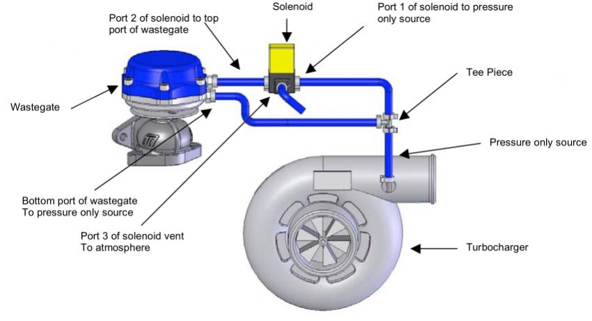
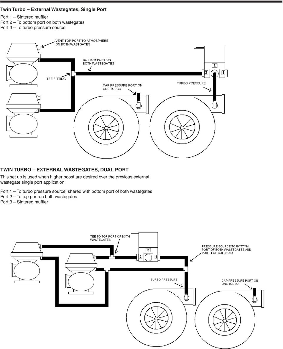
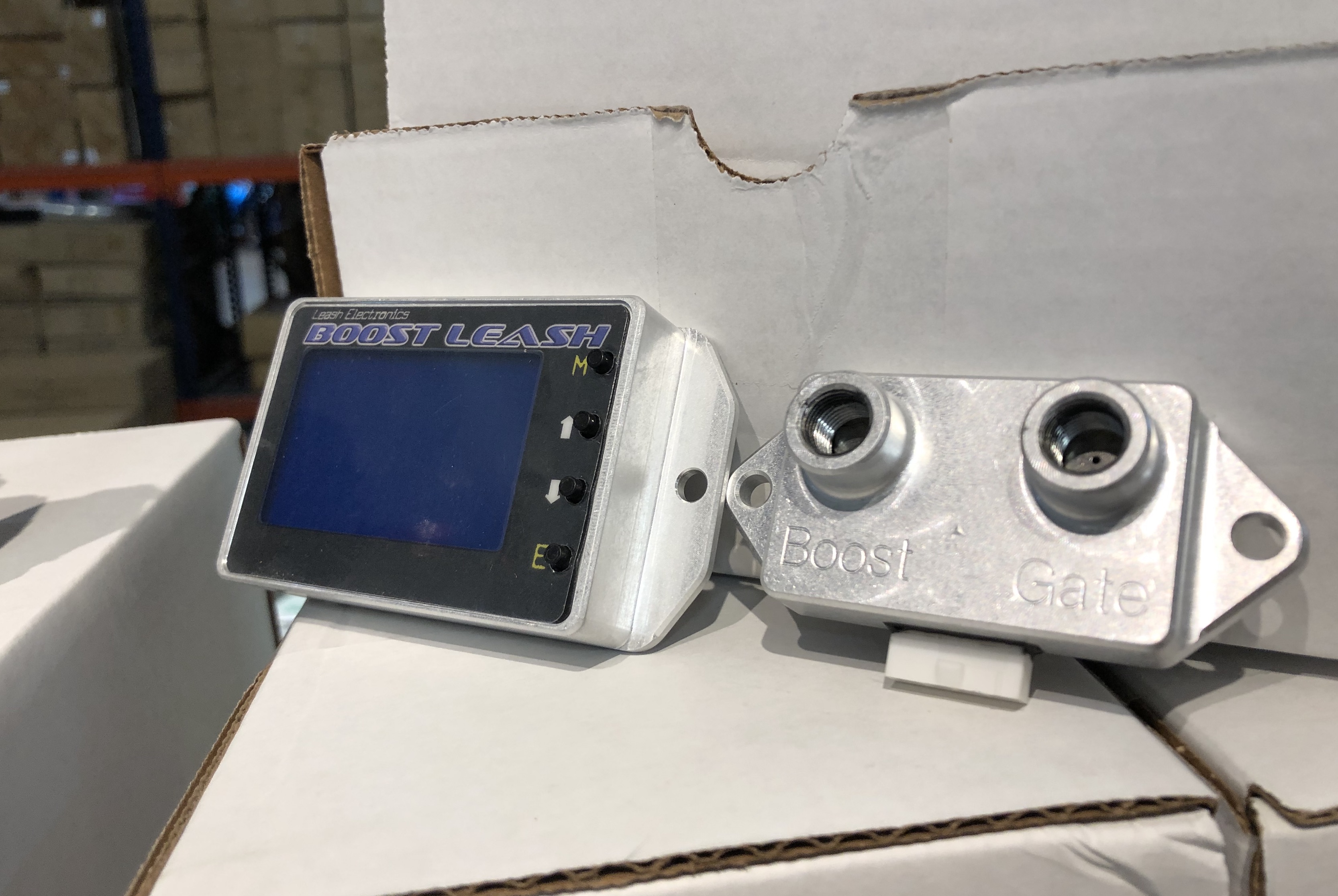
Manual boost controller install bench. Instructions wiring manuals.

Kenne Bell Boost Pump Wiring Help
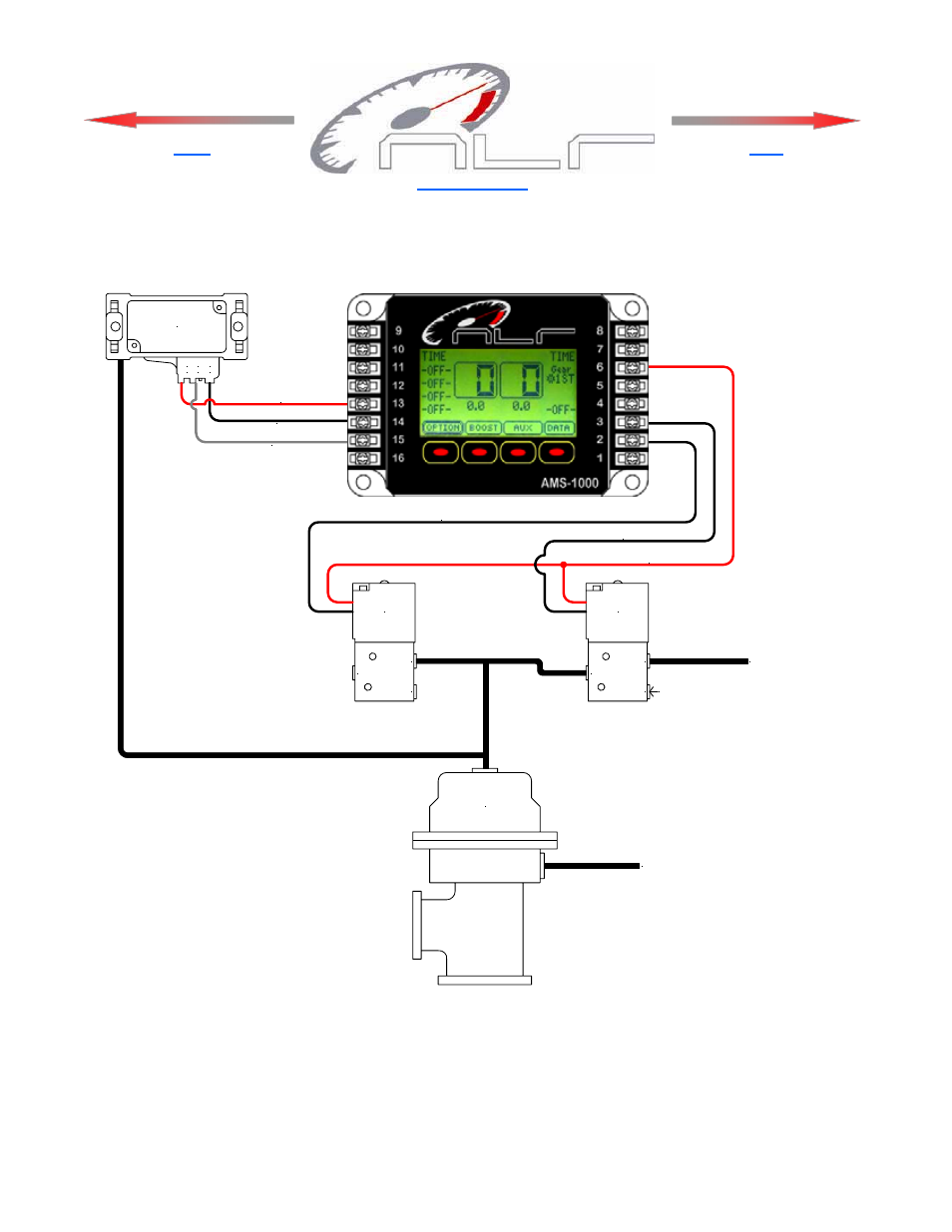
Ams 1000 boost controller wiring diagram. Wiring diagram ground activation page 18. Nlr is the leader in forced induction technology. Wabtec corporation 30 isabella street pittsburgh pa 15212 usa phone. The data is pre sented as a graph with a scroll function for detailed data information. Nms 1000 nitrous management system. The latest development is this controller.
How to properly install wiring for a 24v minn kota trolling motor with a circuit breaker. 15 jan 2014 22 feb 2016 13 nov 2014 to get to the download click add to. Ams 1000 boost controller instruction manual pdf. This controller does what others wish they could do. Important information must use static suppression ignition wires with this controller. Ams 1000 firmware and solenoid upgrade this is a firmwaresoftware upgrade for older controllers that will bring them to 42 software like existing units that have the graphing software option.
Ams 2000 nitrous controller wiring guide page 5 holley driver part 554 111 holley 554 111 high current so l i d st at e drivers are recommended to handle the hi gh current l oads f or ni t rous and fuel solenoids on this system. The nms 1000 nitrous controller contains high frequency digital electronics and will not function correctly without sup. The nlr 1000 input signal is the tp sensor and i wired it to activate the 1 position gps on the controller. Time based 1 to 6 stages fully programmable. Data logging is integrated into the ams 1000 and provides the user with instant feedback on the performance and real time operating parameters. If only the main boost channel is used for control of a waste gate the aux channel map sensor input.
The ams 1000 is the secret the top teams are using and now it is available to you. T he ams 2000 cont rol l er has a 7 amp maximum output current capacit y and t he hol l ey sol i d st at e. Ad i also added two momentary. Download download ams 2000 boost controller instructions read online read online ams 2000 boost controller instructions ams 500 v2 instructions ams 2000 traction control ams 2000 nitrous controller wiring diagram nlr gats ams 1000 boost controller instructions nlr llcams 500 v1 instructions hayabusa boost controller. Ams 1000 graph software. We used to offer this as a free service but many would send in broken units and then blame the upgrade for it not working.
The gear position sensor reads 0 5v so with the voltage points selected at 4 different stages plus adjusting the range allowance between these points the solinoids are running without a dead spot. You are not being. To get to the download click add to cart nothing with show that its added to your cart then continue to checkout then complete order and it will be on the next page that shows up. Ams 1000 boost controller instruction manual pdf.


