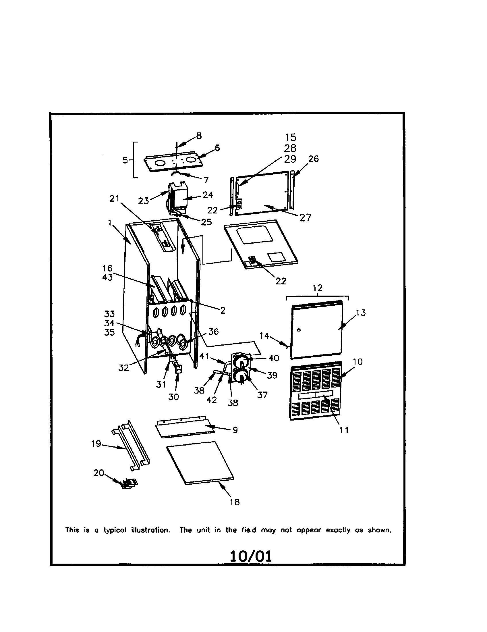
Model number coding system. Wiring diagrams wiring diagrams note.
Trane Wc 150b G Series Installation Operation Amp Maintenance
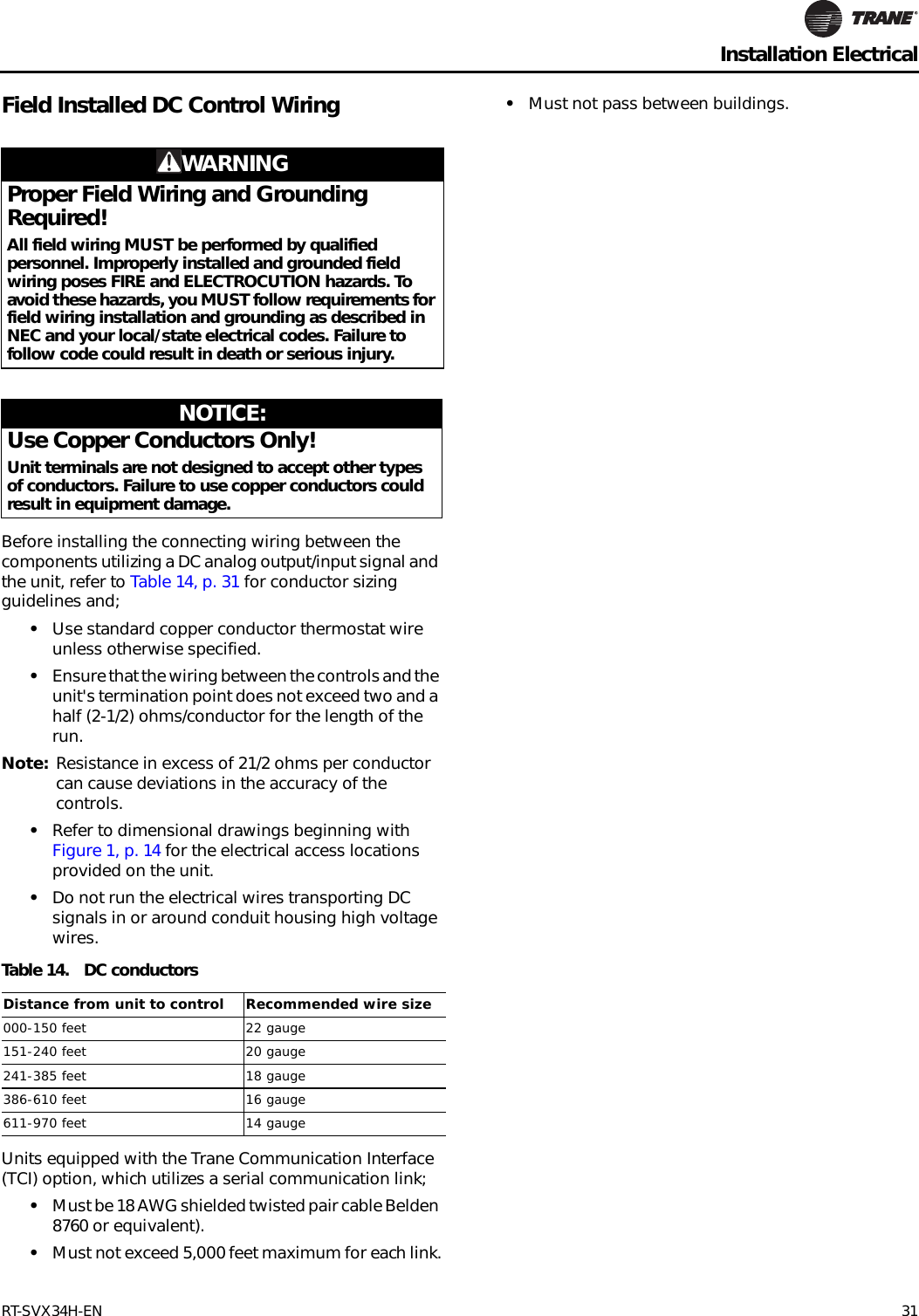
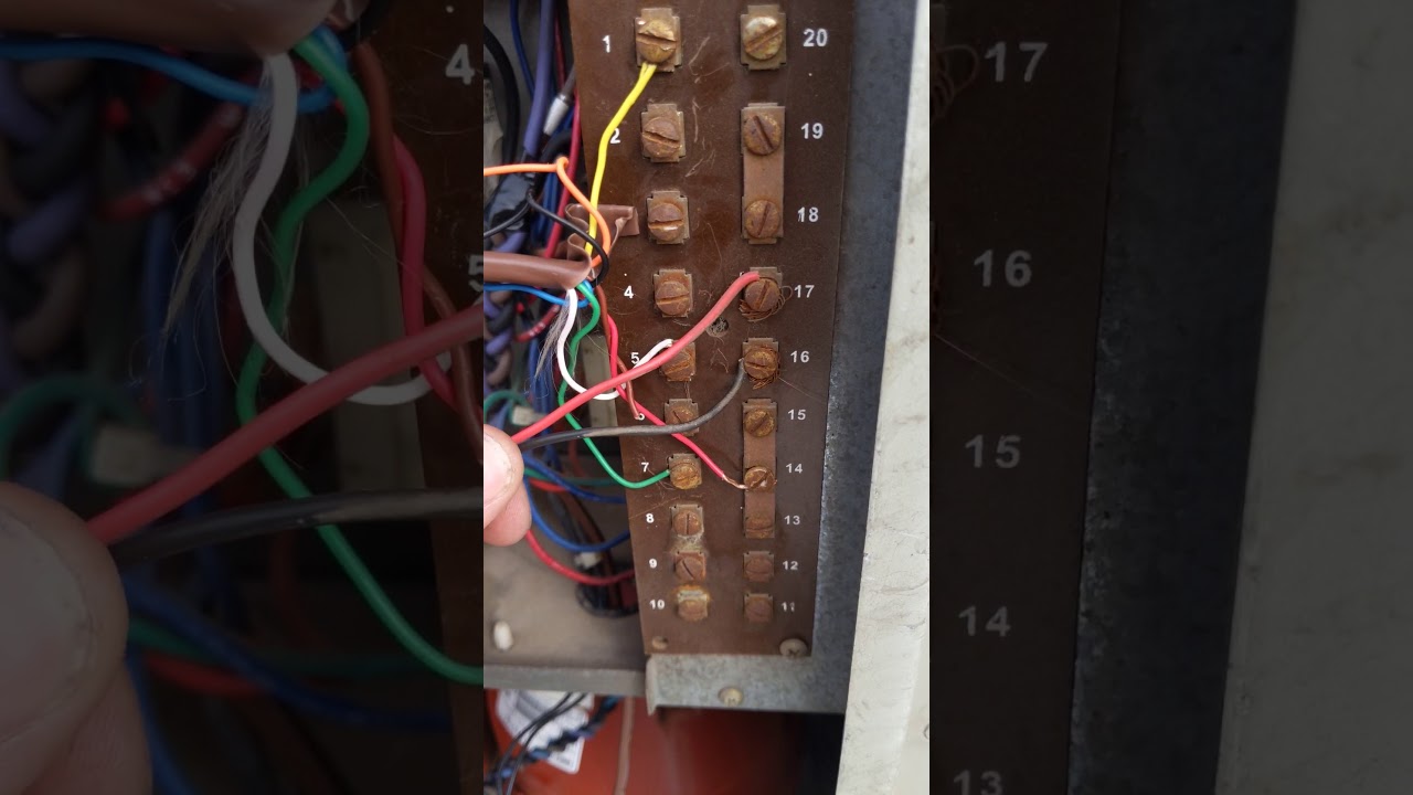
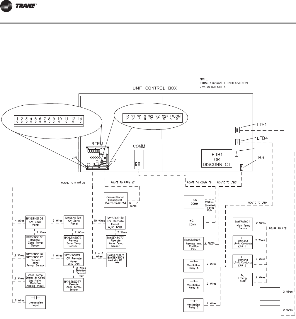
Trane cti wiring diagram. Package air conditioning thermostat wiring. Refrigerant oil trane oil00048. Connect room thermostat to terminal block ltb as shown for the type unit. Trane voyager wiring diagram aka cti. Set up the unit just like the wiring diagram said. See unit wiring diagram for balance of wiring.
Wiring a heat pump thermostat to the air handler and outdoor unit. For easier access published unit wiring diagrams individual separate diagrams for unitary product linesafter 2007 will become available via e library instead of through wiring manuals. Our network of experts extends beyond the counter and guarantees your needs will be met with the most qualified solutions. Cti installation for trane package unit 2000 model. Identifies installation op eration and maintenance and service data literature pueblo. The unit did not seam.
Cti installation for trane package unit 2000 model duration. Lists drawing numbers for unit wiring diagrams pueblo. It is set up with a dc voltage t stat an i am trying to wire in a cti board into the systom so i can use a honeywell pro 8000. Trane voyager wiring diagram aka cti board for thermostat. Hi my name is john im a servic tech i have a 13 year old trane voyager its ac with gas heat. A wiring diagram is a simplified conventional photographic depiction of an electric circuit.
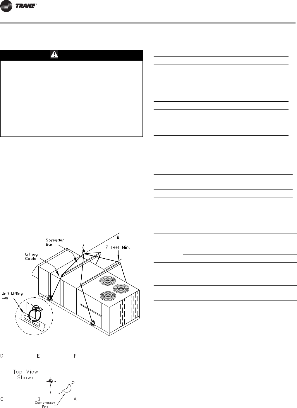
When using a programmable thermostat baystat024 with cti the emergency heat. See figure 1 for typical field wiring. Variety of trane ac wiring diagram. Prior to 2008 wiring diagrams will be in wiring manuals rt sve03a en and rt sve06a en. The model numbers for the unit and the compressor are. Reference materials are at your fingertips 247 here.
Making your job easier is part of what we do by providing you with the information you need quickly. 1998 since the trane company has policy of continuous product improvement it reserves the right to change specifications. Lists unit test pressures. Units equipped with ctis are limited to two stages of cooling. Place wiring diagram label on dead front cover. Cti to j7 of the ucp.
The most recent wiring diagrams prior to beginning any field modifications and consult local. It reveals the parts of the circuit as streamlined shapes and also the power as well as signal connections in between the devices.
Gallery of Trane Cti Wiring Diagram