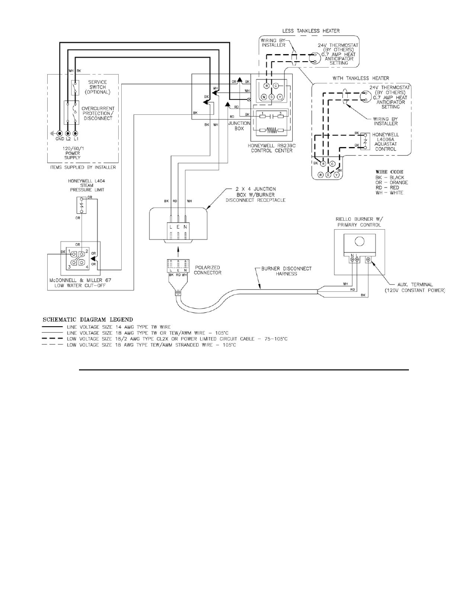
Diagram 1 wf2 u 24 ps 802 lwco wn h ps 801 120 lwco uni match water feeder wf2 u 120 field or factory jumper wire p 12345 connect wire from terminal nof water feeder to terminal 2on lwco. A wiring diagram is a sort of schematic which makes use of abstract pictorial symbols to reveal all the interconnections of elements in a system.
Crown Boiler Bsi138 Boiler User Manual
Mcdonnell miller wf2 u 24 wiring diagram. Mcdonnell miller air flow switches sense air flow or no air flow by responding only to velocity of air movement. The wiring diagrams show connecting the rb 24 on typical burner circuits. Connect wire from terminal hof water feeder to terminal 1on lwco. Note that the control requires a constant source of power with the red hot and white. Wellborn assortment of mcdonnell miller wf2 u 24 wiring diagram. Miller wf2 u 24 wiring diagram sample july 30 2018 march 23 2018 by faceitsalon collection of mcdonnell amp.
Miller wf2 u 24 wiring diagram youll be able to download for free. Mcdonnell miller wf2 u 24v unimatch 24v electric water feeder series wf uni match electric water feeders for low pressure steam boilers with cold water feed three position slide switch allows the timing cycle to be matched to that of the major low water cut off manufacturers field adapters feed rate 1 2 or 4 gpm 38 76 or 151. It reveals the elements of the circuit as simplified forms and the power and signal connections between the gadgets. Mcdonnell miller wf2 u 24 wiring diagram free wiring architectural wiring diagrams affect the approximate locations and interconnections of receptacles lighting and unshakable electrical services in a building. They provide a positive and economical way to detect change or loss of air flow velocity caused by closed damper or fan inlet a loose fan wheel a slipped or broken fan belt a dirty or clogged filter or an overload on a fan motor switch. Enjoy the uni match 24 volt universal water feeder mm wf2 u 24 for mcdonnell miller models is designed for use with a steam boiler at the home depot.
Feeder to neutral wire of burner circuit. Connect wire from terminal h of water grey lines. A wiring diagram is a streamlined standard photographic depiction of an electrical circuit. Basic wiring mcdonnell miller the rb 24 can be used on gas and oil fired boilers with 24 volt control circuit including boilers with spark ignition. Page 4 diagram 5 wiring diagram legends wfe 120 67 with 120 volt burner circuit bold lines indicate action to be taken connect wire from terminal n of water in step shown. Mcdonnell miller wf2 u 24 wiring diagram whats wiring diagram.
Interconnecting wire routes may be shown approximately where particular receptacles or fixtures must be upon a common circuit. Mcdonnell miller uni match wfe 24 instruction manual. August 8 2018 by larry a.
Gallery of Mcdonnell Miller Wf2 U 24 Wiring Diagram