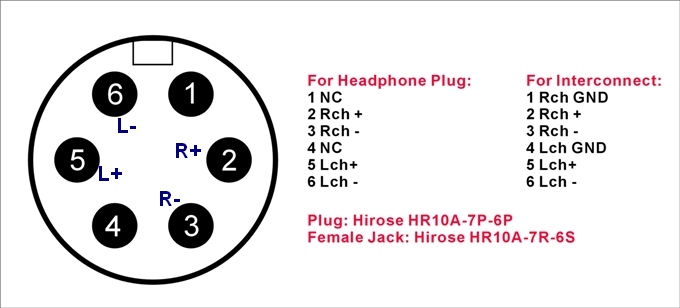
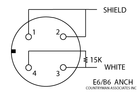
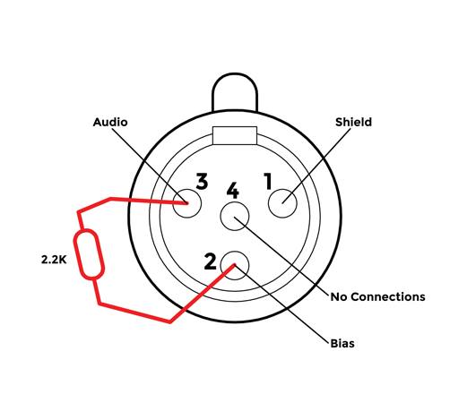
Pin 1 s pin 3 w jumper 1 to 2 27k ohms 3 to 4 diagram. Pin 1 s pin 3 b pin 4 r jumper 1 to 2 use w5 type headset diagram.
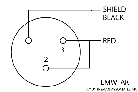
Microphone And Wireless Transmitter Wiring Countryman Com
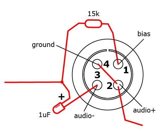
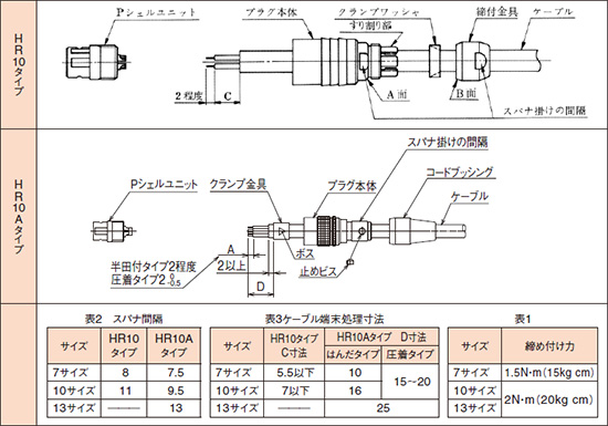
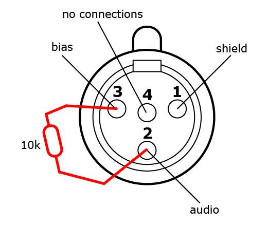
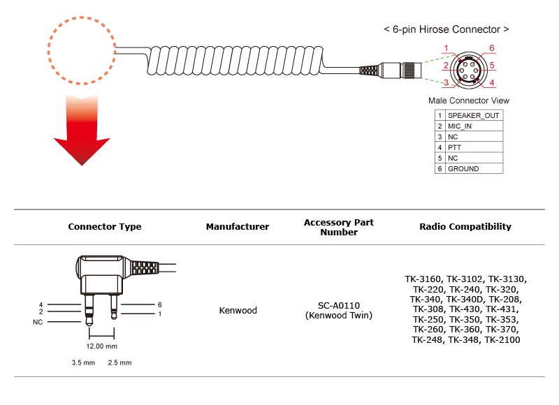
Hirose 4 pin wiring diagram. Pin 1 s pin 3 b pin 4 r jumper 1 to 2 diagram. If you have a third hand or other way to firmly hold the connector. Seemed to work well for himymmv. Installing the 4 pin trailer wires. See wiring diagrams for compatibility with wireless brands. Sony dwt b01 hirose 4 pin connector.
Wait until you try to solder wire to those tiny cups. He just placed the wire above the cup heated the cup and pushed the wire in. Note that this type of 4 pin connector is less common that 4 pin flat connector. Depending on the size of your trailer and the number of lights you might want to check on the internet for the recommended gauge for your specific trailer. Start by cutting the white wire and attaching it to the trailer frame. I cant find anywhere for a proper diagram for the pin configuration of the hirose 4 pin power connector.
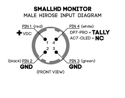
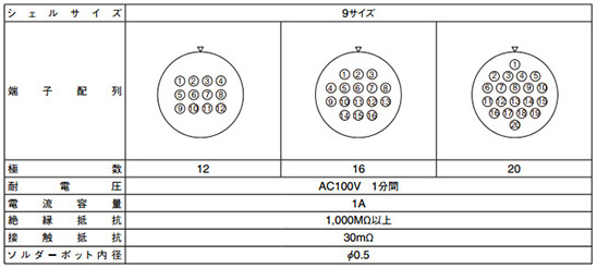
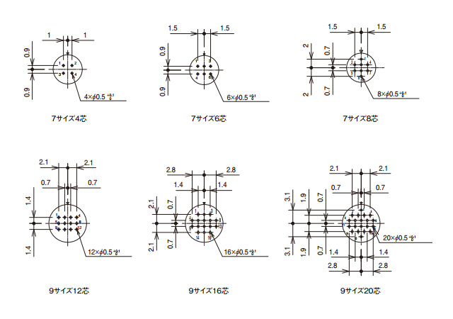
Hirose electric co ltd. Yellow and green are for left and right turns and braking. Pin 1 gets the ground pins 2 3 are not connected and pin 4 gets the positive dc power. Below is the generic schematic of how the wiring goes. Could someone tell me which pin is 4 and 1 when looking at the connector from the solder points with the keystone on top. The way it is you have a 5050 shot at getting it right.
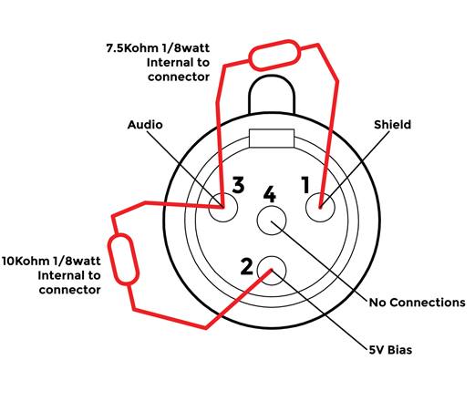
Pin 1 s pin 3 w jumper. This type of connector is normally found on utvs atvs and trailers that do not have their own braking system. 4 pin trailer wiring diagram. Point source audio microphones are compatible with many popular wireless microphone systems. Buy a 4 pin wiring kit with wires at least twenty feet in length so its long enough for your trailer. Is a leading global supplier of innovative interconnects employing advanced engineering services superior customer support and worldwide manufacturing capabilities to p.
Hirose electric co ltd. They need to send diagrams with these small connectors. You can search hiroses connector for product series. Pin 1 s pin 3 b pin 4 r jumper 1 to 2 diagram. Above we have describes the main types of trailer wiring diagrams. The most common wire thickness for a trailer is 16 gauge but i bought thicker wiring for added durability.
For ease of wiring i like to start by soldering wire pigtails to the appropriate pins on each hirose power connector. Is a leading global supplier of innovative interconnects employing advanced engineering services superior customer support and worldwide manufacturing capabilities to provide value based connector solutions for various industri. The next step is wiring the whole thing up. We ended up pre tinning all the wires and one of us even prefilled the cups with solder too. You must check the trailer manual to see if the wiring is correct but normally the white wire is called the ground wire while the brown wire is used for tail lights. See wiring diagrams for compatibility with wireless brands.
Gallery of Hirose 4 Pin Wiring Diagram