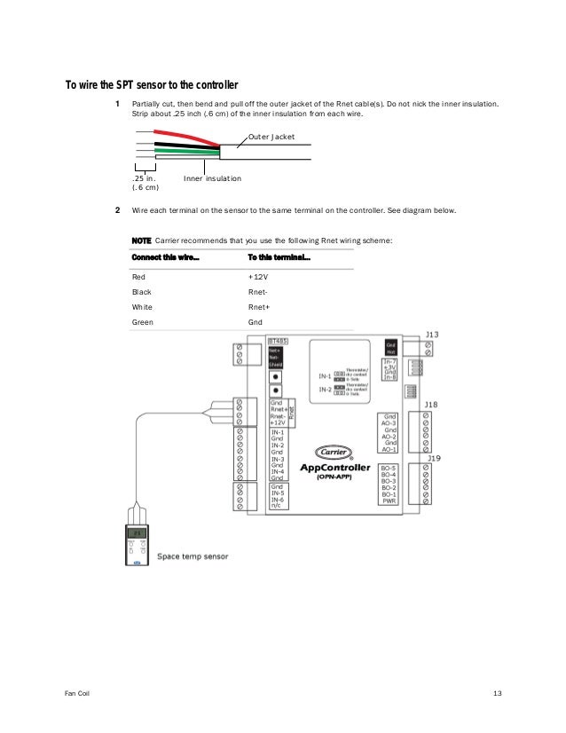
If an ansul fire system is present the fire system micro switch will need to be wired to terminals as indicated on the installation diagram typically c1 and ar1. Incorrect polarity negates the sensor signal.
Carrier 50tfq008 012 Users Manual
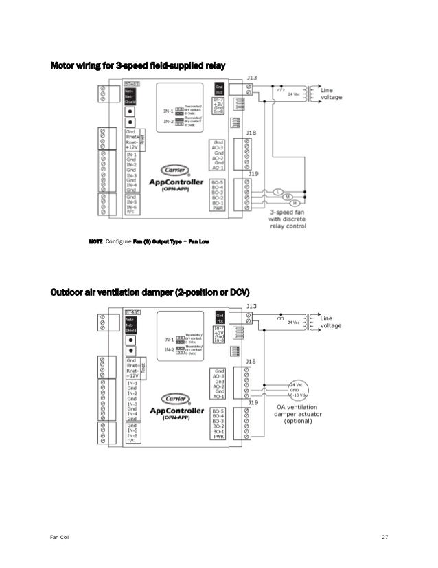
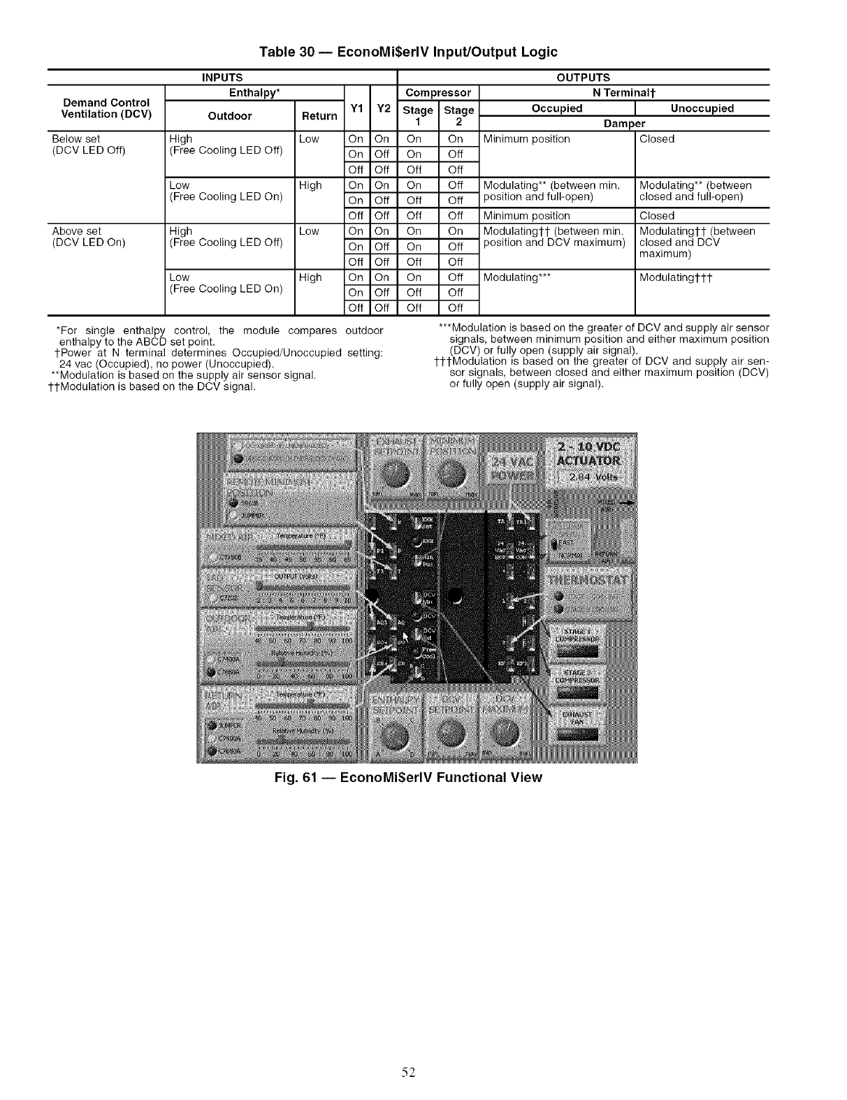
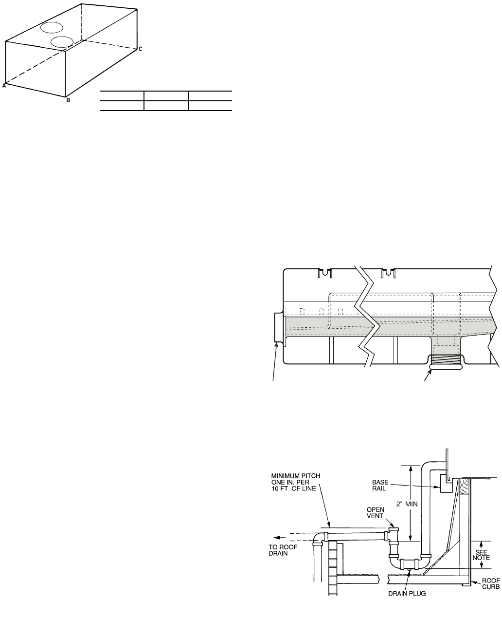
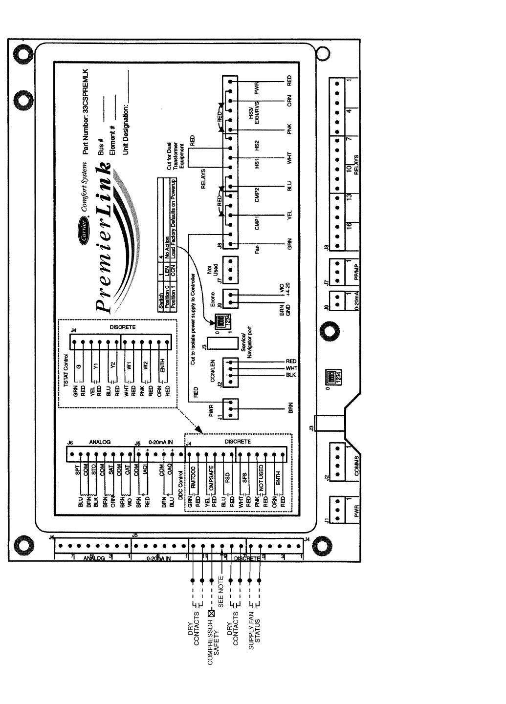
Dcv 1111 wiring diagram. In this post i am just tell you about wiring of single epo button with shunt trip mccb breaker. Large inspection doors simplifies inspection and service. 8 or newer e d c b a enthalpy setpoint design dcv min pos dcv mode p p1 dcv rah rat oat oah mat exf. All device inputs and outputs must be 24 vac class 2. All wiring must comply with applicable local codes ordinances and regulations. 13 gasket collector box 1065210 1111 111111111111 14 box collector 1098340 1111 111111111111 11114 1111111111111 r 0 e 7 w 0 o 6 l b n o i t s u b m o c t e k s a g 5 1 16 blower combustion 1054268 1111 111111111111.
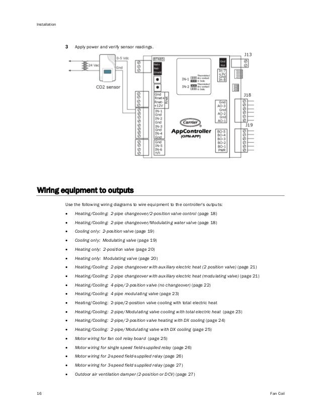
A svc speaker has one voice coil and one set of terminals one positive and one negative. Refer to table 2 for a list of the wiring diagrams and corresponding figure numbers in this document. Ensure proper polarity of sensor connections. Dcvb units are designed for installation on wall in laundry rooms utility rooms or similar. Wiring diagram index name description page aa power distribution frc 3 ab power distribution frc 4 ac power supply circuit protection 34 ef 5 ad power supply circuit protection 44 ef 6 ae grounding 7 af starting and charging 8. Because of this dvc speakers typically subwoofers offer.
Prot ocol interface co nt roller modbus rx tx rs232. Dcv setpoint rtrm v. The following wiring diagram applies for units equipped with reliatelcontroller with the tci communication interface. In industrial state electric operator duty is to operate the machinery and his duty is on the front of main panel board. This subwoofer wiring application includes diagrams for single voice coil svc and dual voice coil dvc speakers. C1 is common and.
With the white painted door and side panels the unit can easily be installed to blend in with the surroundings. The hood light wiring will also need to be wired to terminals as indicated on the installation diagram. The vr 400 dcvb has a by pass function which allows the unit to be connected. Diagrams inside the panel for details. Parts list wiring diagrams for pgb pgmf series. Shunt trip breaker wiring diagram with epo button.
Quick start guide d103556x012 dvc6200 digital valve controllers june 2019 6 slidingstem linear actuators bracket mounted fisher 667 and 657 1. Isolate the control valve from the process line pressure and release pressure from both sides of the valve body. Casservice explains how to wire the exhaust hood fire system microswitch to an exhaust hood control package. A dvc speaker has two voice coils each with its own set of terminals.
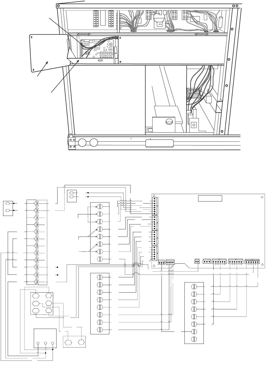
Gallery of Dcv 1111 Wiring Diagram